BACK DOOR DISASSEMBLY
CAUTION / NOTICE / HINT
The necessary procedures (adjustment, calibration, initialization, or registration) that must be performed after parts are removed and installed, or replaced during back door removal/installation are shown below.
| Replaced Part or Performed Procedure | Necessary Procedure | Effect/Inoperative Function when Necessary Procedure not Performed | Link |
|---|---|---|---|
| Rear television camera assembly |
|
Parking assist monitor system |
PROCEDURE
-
REMOVE BACK DOOR UPPER TRIM PANEL ASSEMBLY
-
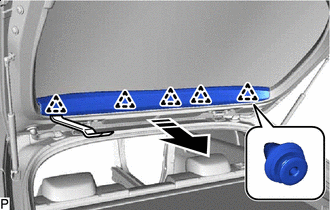

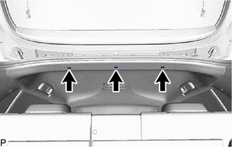
Remove in this Direction Using a moulding remover, disengage 5 clips to remove the back door upper trim panel assembly as shown in the illustration.
-
-
REMOVE DOOR PULL HANDLE
-
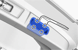
Using a moulding remover, disengage the 4 claws to remove the door pull handle.
Tech Tips
Use the same procedure for the RH side and LH side.
-
-
REMOVE BACK DOOR TRIM BOARD ASSEMBLY
-
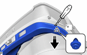
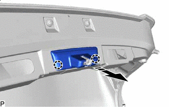
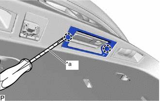
*a Protective Tape Remove in this Direction Using a screwdriver with its tip wrapped with protective tape, disengage the clip as shown in the illustration.
-
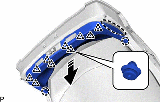

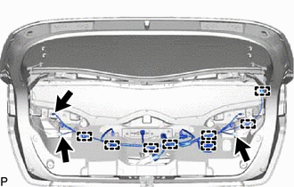
Place Hand Here Remove in this Direction Disengage the 10 clips and 2 claws to remove the back door trim board assembly as shown in the illustration.
-
-
REMOVE BACK DOOR LOCK COVER
-
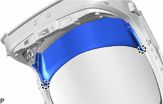
Remove in this Direction Disengage the 2 claws to remove the back door lock cover as shown in the illustration.
-
-
REMOVE BACK DOOR TRIM BOARD
-

Remove the 2 clips.
-
Disengage the 2 claws.
-
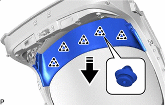
Remove in this Direction Disengage the 5 clips to remove the back door trim board as shown in the illustration.
-
-
REMOVE BACK DOOR LOCK ASSEMBLY
-
REMOVE BACK DOOR LOWER STOPPER
Tech Tips
Use the same procedure for the RH side and LH side.
-
Remove the bolt.
-
Disengage the guide to remove the back door lower stopper.
-
-
REMOVE BACK DOOR OUTSIDE GARNISH ASSEMBLY
-
REMOVE CENTER STOP LIGHT SET
-
REMOVE REAR LIGHT ASSEMBLY LH
-
REMOVE REAR LIGHT ASSEMBLY RH
Tech Tips
Use the same procedure as for the LH side.
-
REMOVE BACK DOOR OPENER SWITCH ASSEMBLY
-
REMOVE BACK DOOR NO. 1 FINISH PANEL PROTECTOR
-
*a Protective Tape Using a screwdriver with its tip wrapped with protective tape, disengage the 2 claws to remove the back door No. 1 finish panel protector.
-
-
REMOVE BACK DOOR FINISH PANEL COVER
Tech Tips
Use the same procedure for the RH side and LH side.
-
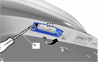
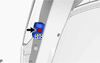
*a Protective Tape Remove in this Direction Using a screwdriver with its tip wrapped with protective tape, disengage the 2 claws as shown in the illustration.
-
Disengage the guide to remove the back door finish panel cover as shown in the illustration.
-
-
REMOVE LICENSE PLATE LIGHT ASSEMBLY
-
REMOVE REAR TELEVISION CAMERA ASSEMBLY
-
REMOVE BACK DOOR PANEL CUSHION
-
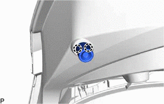
Disengage the 2 claws to remove the back door panel cushion.
Tech Tips
Use the same procedure for the RH side and LH side.
-
-
REMOVE BACK DOOR STAY ASSEMBLY LH
-
REMOVE BACK DOOR STAY ASSEMBLY RH
Tech Tips
Use the same procedure as for the LH side.
-
REMOVE BACK DOOR STAY BOLT
-
REMOVE TONNEAU COVER ASSEMBLY
-
REMOVE REAR NO. 2 FLOOR BOARD
-
REMOVE REAR NO. 4 FLOOR BOARD
-
REMOVE REAR NO. 3 FLOOR BOARD
-
REMOVE REAR NO. 1 FLOOR BOARD
-
REMOVE DECK FLOOR BOX LH
-
REMOVE DECK FLOOR BOX RH
-
REMOVE DECK TRIM SERVICE HOLE COVER
-
REMOVE REAR DECK TRIM COVER
-
REMOVE REAR SEAT HEADREST ASSEMBLY
-
REMOVE REAR SEATBACK ASSEMBLY LH
-
REMOVE REAR SEAT CUSHION ASSEMBLY LH
-
REMOVE REAR SEAT CUSHION LOCK HOOK
-
REMOVE REAR DOOR SCUFF PLATE LH
-
DISCONNECT REAR DOOR OPENING TRIM WEATHERSTRIP LH
-
Disconnect the rear door opening trim weatherstrip LH.
-
-
REMOVE REAR UNDER SIDE COVER LH
-
REMOVE REAR SEATBACK HINGE SUB-ASSEMBLY LH
-
REMOVE REAR SEAT SIDE GARNISH LH
-
REMOVE ROPE HOOK (w/o Toyota Safety Sense)
-
REMOVE NO. 2 ROPE HOOK (w/o Toyota Safety Sense)
-
REMOVE NO. 1 TONNEAU COVER HOLDER CAP (w/ Toyota Safety Sense)
-
REMOVE TONNEAU COVER HOOK A (w/ Toyota Safety Sense)
-
REMOVE DECK TRIM SIDE PANEL ASSEMBLY LH
-
REMOVE ROOF SIDE INNER GARNISH ASSEMBLY LH
-
REMOVE BACK DOOR NO. 1 WIRE
-
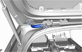
Disengage the 8 claws to separate the 2 grommets.
Note
When reusing the back door No. 1 wire, make sure to replace the 2 No. 4 wiring harness protectors with new ones as reusing them may cause water ingress.
-
Remove the 3 clips.
-
Disconnect the 2 connectors.
-
Disengage the 2 clamps.
-
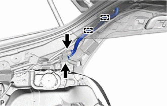
Pull the back door No. 1 wire as shown in the illustration.
-
Disconnect the 2 connectors.
-
Secure a rope to the back door No. 1 wire with vinyl tape as shown in the illustration.
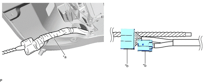
*a Vinyl tape *b Connector Note
Make sure that the rope is secured with vinyl tape to prevent the rope from separating from the back door No. 1 wire when removing it.
-
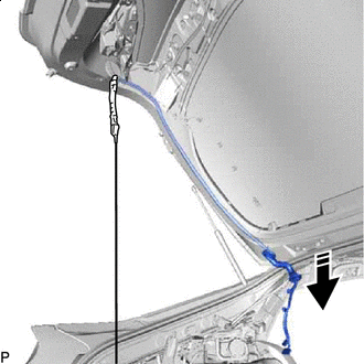
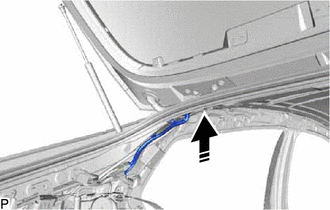
Remove in this Direction Remove the back door No. 1 wire as shown in the illustration.
Note
-
The rope will be used when installing the back door No. 1 wire. Leave the rope inside the back door panel sub-assembly.
-
This step should not be performed with the back door panel sub-assembly removed from the vehicle.
Tech Tips
The back door No. 1 wire is likely to be caught on the parts of the back door panel sub-assembly. If the back door No. 1 wire is caught, gradually remove it by moving it back and forth, or by turning it.
-
-
When reusing the back door No. 1 wire:
Tech Tips
Use the same procedure for both No. 4 wiring harness protectors.
-
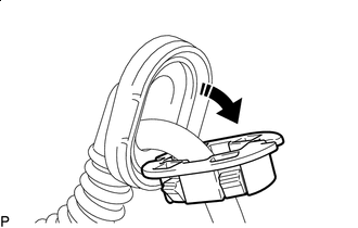
Remove in this Direction Separate the No. 4 wiring harness protector from the grommet as shown in the illustration.
-
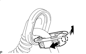
Remove in this Direction Disengage the claw as shown in the illustration and remove the No. 4 wiring harness protector.
-
-
-
REMOVE BACK DOOR NO. 2 WIRE
-
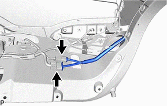
Disconnect the 3 connectors.
-
Disengage the 8 clamps to remove the back door No. 2 wire.
-