FRONT DOOR REASSEMBLY

CAUTION / NOTICE / HINT
Tech Tips
-
Use the same procedure for the RH side and LH side.
-
The following procedure is for the LH side.
PROCEDURE
-
PRECAUTION
Note
After turning the power switch off, waiting time may be required before disconnecting the cable from the negative (-) auxiliary battery terminal. Therefore, make sure to read the disconnecting the cable from the negative (-) auxiliary battery terminal notices before proceeding with work.
-
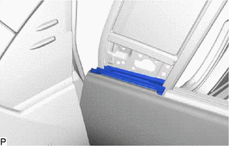
INSTALL FRONT DOOR FRONT WINDOW FRAME MOULDING
-
INSTALL COWL SIDE TRIM BOARD
-
INSTALL FRONT DOOR SCUFF PLATE
-
REPAIR INSTRUCTION (w/ Black Out Tape)
-
INSTALL FRONT DOOR LOWER OUTSIDE STRIPE (w/ Black Out Tape)
-
INSTALL FRONT DOOR STRIPE (w/ Black Out Tape)
-
INSTALL FRONT DOOR REAR OUTSIDE STRIPE (w/ Black Out Tape)
-
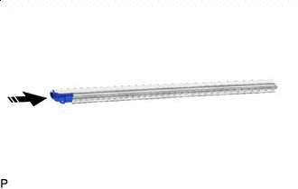
INSTALL FRONT DOOR UPPER WINDOW FRAME MOULDING
-
INSTALL FRONT DOOR REAR WINDOW FRAME MOULDING
-
INSTALL FRONT DOOR BELT MOULDING ASSEMBLY
-
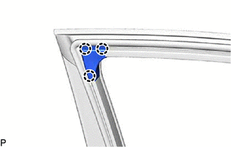
INSTALL FRONT DOOR DUST PROOF SEAL
-
Engage the 3 claws to install 3 new front door dust proof seals.
-
-
INSTALL FRONT DOOR PANEL CUSHION
-
Engage the 4 claws to install 2 new front door panel cushions.
-
-
INSTALL FRONT DOOR FIX WINDOW GLASS
-
Install the front door fix window glass to the front door fix window weatherstrip.
-

Install in this Direction Install the front door fix window glass with the front door fix window weatherstrip as shown in the illustration.
-
-
INSTALL FRONT DOOR FRONT LOWER FRAME SUB-ASSEMBLY
-

Bolt 
Screw Install the front door front lower frame sub-assembly with the 3 bolts and screw.
- Torque:
- Bolt
- 8.5 N*m { 87 kgf*cm, 75 in.*lbf }
- Screw
- 3.1 N*m { 32 kgf*cm, 27 in.*lbf }
-
-
INSTALL DOOR FRAME GARNISH
-
Engage the 3 claws to install the door frame garnish.
-
-
INSTALL FRONT DOOR WEATHERSTRIP
-
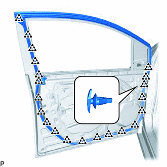
Engage the 21 clips and install the front door weatherstrip.
-
-
INSTALL FRONT DOOR CHECK ASSEMBLY
-
Apply MP grease to the sliding parts of the front door check assembly.
-
Clean the bolt hole in the vehicle body.
-
Clean the threads of the bolt (B).
-
Apply adhesive to the threads of the bolt (B).
Adhesive Toyota Genuine Adhesive 1324, Three Bond 1324 or equivalent -
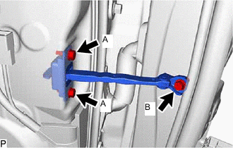
Install the front door check assembly with the 3 bolts.
- Torque:
- Bolt (A)
- 5.5 N*m { 56 kgf*cm, 49 in.*lbf }
- Bolt (B)
- 30 N*m { 306 kgf*cm, 22 ft.*lbf }
-
-
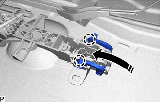
INSTALL FRONT DOOR LOCK OPEN ROD
-
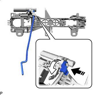
Install in this Direction (1) 
Install in this Direction (2) Install the front door lock open rod as indicated by the arrows, in the order shown in the illustration.
-
-
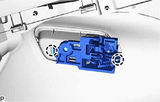
INSTALL FRONT DOOR OUTSIDE HANDLE FRAME SUB-ASSEMBLY
-
Apply MP grease to the sliding parts on the front door outside handle frame sub-assembly.
-
*A Outside *B Inside Engage the claw as shown in the illustration.
-
Using a T30 "TORX" socket wrench, install the front door outside handle frame sub-assembly with the screw.
- Torque:
- 4.0 N*m { 41 kgf*cm, 35 in.*lbf }
-
-
INSTALL FRONT DOOR LOCK WITH MOTOR ASSEMBLY
-
INSTALL FRONT DOOR REAR OUTSIDE HANDLE PAD
-
Engage the 3 guides.
-
Engage the claw to install the front door rear outside handle pad.
-
-
INSTALL FRONT DOOR FRONT OUTSIDE HANDLE PAD
-
Engage the 3 claws to install the front door front outside handle pad.
-
-
INSTALL FRONT DOOR OUTSIDE HANDLE COVER (for Front Passenger Side)
-
Engage the 2 guides and claw.
-
Using a T30 "TORX" socket wrench, install the front door outside handle cover with the screw.
- Torque:
- 4.0 N*m { 41 kgf*cm, 35 in.*lbf }
-
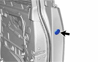
Install the hole plug.
-
-
INSTALL FRONT DOOR LOCK CYLINDER ASSEMBLY (for Driver Side)
-
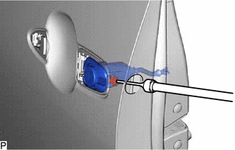
Using a T30 "TORX" socket wrench, install the front door lock cylinder assembly with the screw.
- Torque:
- 4.0 N*m { 41 kgf*cm, 35 in.*lbf }
-
Install the hole plug.
-
-
INSTALL FRONT DOOR OUTSIDE HANDLE ASSEMBLY
-
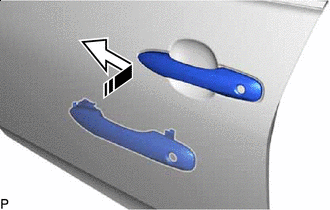
Install in this Direction Insert the front end of the front door outside handle assembly into the front door outside handle frame sub-assembly.
-
Insert the rear end of the front door outside handle assembly into the front door outside handle frame sub-assembly, then slide the front door outside handle assembly toward the front of the vehicle to install it.
-
Engage in this Direction Move the lever as shown in the illustration and engage the 2 claws to secure the front door outside handle assembly.
-
Engage the 3 clamps.
-
Connect the connector.
-
Engage the 2 claws.
-
-
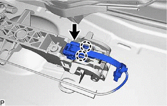
INSTALL FRONT DOOR REAR LOWER FRAME SUB-ASSEMBLY
-
Install in this Direction Engage the guide as shown in the illustration.
-
Install the front door rear lower frame sub-assembly with the bolt.
- Torque:
- 8.5 N*m { 87 kgf*cm, 75 in.*lbf }
-
-
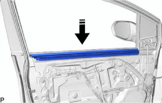
INSTALL FRONT DOOR GLASS RUN
-
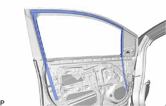
Install the front door glass run.
-
-
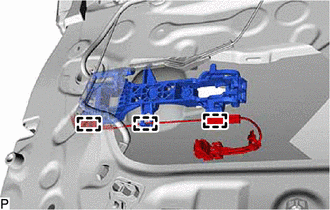
INSTALL FRONT DOOR WINDOW REGULATOR ASSEMBLY
-
Apply MP grease to the sliding parts of the front door window regulator assembly.
-
Temporarily install the temporary bolt to the front door window regulator assembly.
-
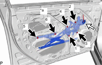
*a Temporary Bolt Temporarily install the front door window regulator assembly with the 5 bolts.
-
Tighten the temporary bolt and 5 bolts to install the front door window regulator assembly.
Tech Tips
Tighten the bolts in the order shown in the illustration.
- Torque:
- 8.0 N*m { 82 kgf*cm, 71 in.*lbf }
-
Connect the connector.
-
Engage the 2 claws to install the front door No. 2 service hole cover.
-
-
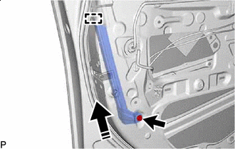
INSTALL FRONT DOOR GLASS SUB-ASSEMBLY
-
for Driver Side:
-
Connect the multiplex network master switch assembly.
-
-
for Front Passenger Side:
-
Connect the power window regulator switch assembly.
-
-
Connect the cable to the negative (-) auxiliary battery terminal.
-
Turn the power switch on (IG).
-
Move the front door window regulator assembly so that the door glass bolt holes can be seen.
-
Turn the power switch off.
-
Disconnect the cable from the negative (-) auxiliary battery terminal.
-
for Driver Side:
-
Disconnect the multiplex network master switch assembly.
-
-
for Front Passenger Side:
-
Disconnect the power window regulator switch assembly.
-
-
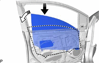
Install in this Direction (1) Install in this Direction (2) Insert the front door glass sub-assembly into the front door panel along the front door glass run as shown in the illustration.
-
Install the front door glass sub-assembly with the 2 bolts.
- Torque:
- 8.0 N*m { 82 kgf*cm, 71 in.*lbf }
-
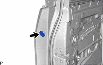
Install the hole plug.
-
-
INSTALL DOOR SIDE AIRBAG SENSOR
-
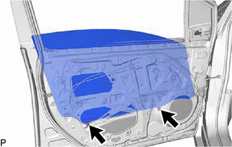
INSTALL FRONT DOOR SERVICE HOLE COVER
-
Engage the 4 clips to install the front door service hole cover.
-
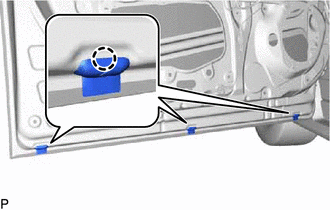
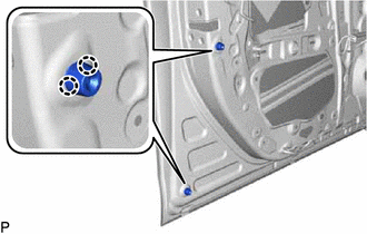
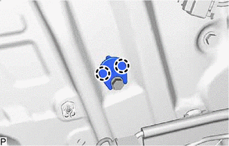
Insert 3 front door weatherstrip clips and turn them 45 degrees as shown in the illustration to install them.
-
-
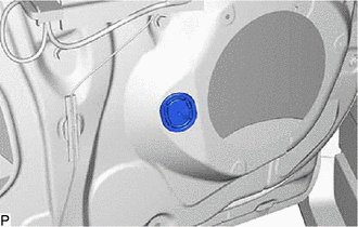
INSTALL FRONT NO. 1 SPEAKER ASSEMBLY
-
INSTALL FRONT DOOR NO. 3 SERVICE HOLE COVER
-
Install the front door No. 3 service hole cover.
-
-
INSTALL OUTER REAR VIEW MIRROR ASSEMBLY
-
INSTALL FRONT DOOR PANEL PROTECTOR
-
INSTALL FRONT DOOR VENT SEAL
-
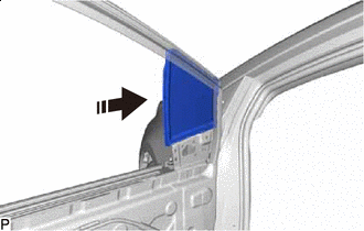
Install in this Direction Install the front door vent seal to the front door inner glass weatherstrip.
-
-
INSTALL FRONT DOOR INNER GLASS WEATHERSTRIP
-
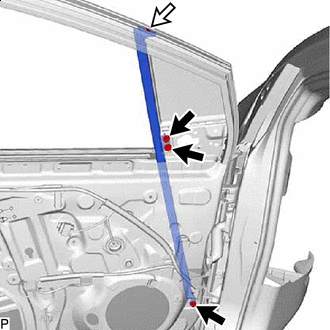
Install in this Direction Install the front door inner glass weatherstrip with front door vent seal as shown in the illustration.
-
-
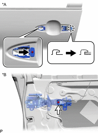
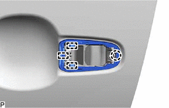
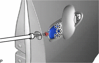
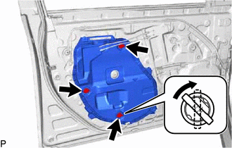
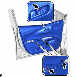
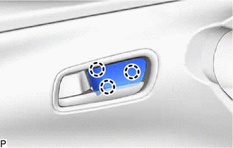
INSTALL FRONT DOOR INSIDE HANDLE SUB-ASSEMBLY
-
Engage the 2 claws to install the front door inside handle sub-assembly.
-
-
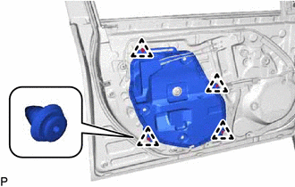
INSTALL FRONT DOOR TRIM BOARD SUB-ASSEMBLY
-
Engage the clip.
-
*1 Front Door Inside Locking Cable Assembly *2 Front Door Lock Remote Control Cable Assembly Install in this Direction Connect the front door lock remote control cable assembly and front door inside locking cable assembly to the front door inside handle sub-assembly as shown in the illustration.
-
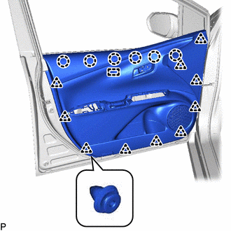
Engage the guide and 6 claws.
-
Engage the 10 clips to install the front door trim board sub-assembly.
-
Install the 3 screws.
-
-
INSTALL COURTESY LIGHT ASSEMBLY
-
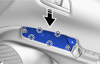
INSTALL MULTIPLEX NETWORK MASTER SWITCH ASSEMBLY WITH FRONT DOOR UPPER ARMREST BASE PANEL (for Driver Side)
-
Connect the connector.
-
Install in this Direction Engage the 2 clips and 4 claws to install the multiplex network master switch assembly with front door upper armrest base panel as shown in the illustration.
-
-
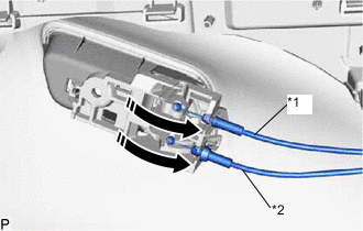
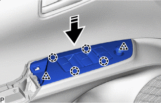
INSTALL POWER WINDOW REGULATOR SWITCH ASSEMBLY WITH FRONT DOOR UPPER ARMREST BASE PANEL (for Front Passenger Side)
-
Connect the connector.
-
Install in this Direction Engage the 2 clips and 4 claws to install the power window regulator switch assembly with front door upper armrest base panel as shown in the illustration.
-
-
INSTALL FRONT ARMREST ASSEMBLY
-
Install in this Direction Engage the guide as shown in the illustration.
-
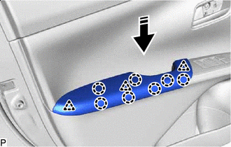
Install in this Direction Engage the 3 clips and 7 claws to install the front armrest assembly as shown in the illustration.
-
-
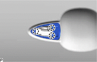
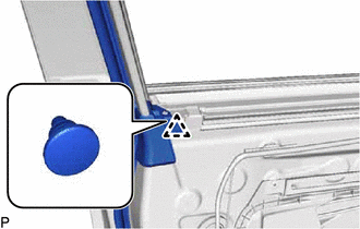
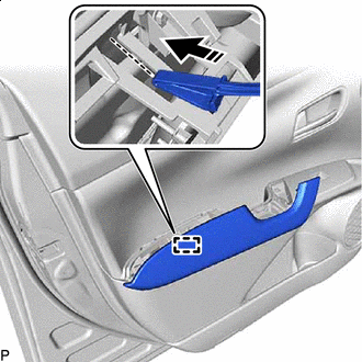
INSTALL FRONT DOOR INSIDE HANDLE BEZEL PLUG
-
Engage the 3 claws to install the front door inside handle bezel plug.
-
-
CONNECT CABLE TO NEGATIVE AUXILIARY BATTERY TERMINAL
Note
When disconnecting the cable, some systems need to be initialized after the cable is reconnected.
-
INITIALIZE POWER WINDOW CONTROL SYSTEM
-
INSPECT POWER WINDOW OPERATION
-
INSPECT SRS WARNING LIGHT