POWER MIRROR CONTROL SYSTEM Power Retractable Mirrors do not Operate with Power Retract Mirror Switch
DESCRIPTION
The outer mirror switch assembly sends a mirror retract/return signal to the main body ECU (multiplex network body ECU) when the retractable outer mirror switch on the outer mirror switch assembly is operated. The main body ECU (multiplex network body ECU) retracts or returns the outer rear view mirror assemblies based on the signal.
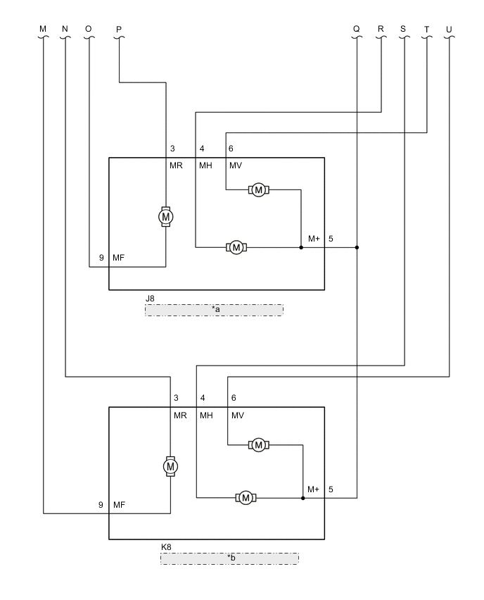
WIRING DIAGRAM
Figure 1. for RHD
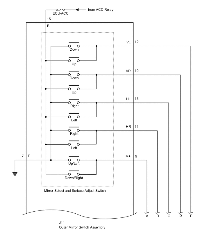
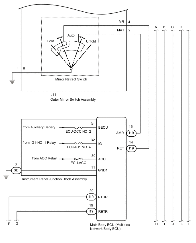
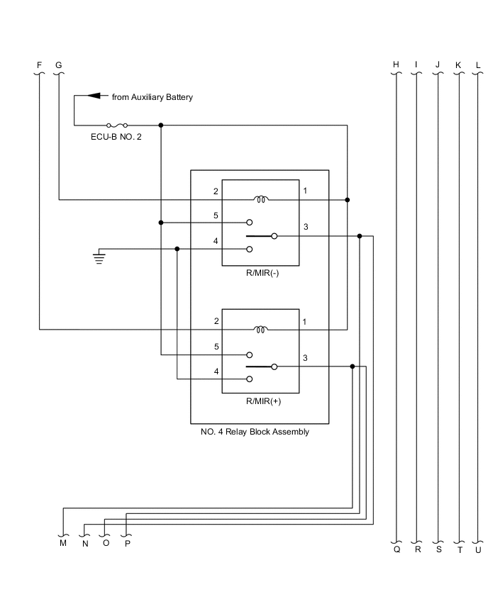
| *a | Outer Rear View Mirror Assembly RH |
| *b | Outer Rear View Mirror Assembly LH |
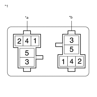
Figure 2. for LHD
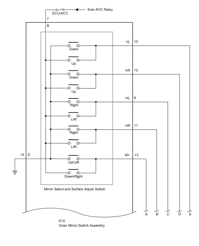


| *a | Outer Rear View Mirror Assembly RH |
| *b | Outer Rear View Mirror Assembly LH |
CAUTION / NOTICE / HINT
Note
-
Inspect the fuses for circuits related to this system before performing the following procedure.
-
If the main body ECU (multiplex network body ECU) is replaced, refer to Service Bulletin.
PROCEDURE
-
READ VALUE USING GTS
-
Connect the GTS to the DLC3.
-
Turn the power switch on (IG).
-
Turn the GTS on.
-
Enter the following menus: Body Electrical / Main Body / Data List.
-
Read the Data List according to the display on the GTS.
Body Electrical > Main Body > Data ListTester Display Measurement Item Range Normal Condition Diagnostic Note Outer Mirror Fold SW Retractable outer mirror switch signal OFF or ON OFF: Retractable outer mirror switch off
ON: Retractable outer mirror switch on
-
Body Electrical > Main Body > Data ListTester Display Outer Mirror Fold SW OK On the GTS screen, ON or OFF is displayed accordingly. Result Proceed to OK NG
NG 
INSPECT OUTER MIRROR SWITCH ASSEMBLY Click here
OK 
-
-
CHECK MALFUNCTIONING PARTS
-
Check the malfunctioning parts.
Result Result Proceed to Both outer rear view mirror assemblies are malfunctioning A Outer rear view mirror assembly LH is malfunctioning B Outer rear view mirror assembly RH is malfunctioning C
B
INSPECT OUTER REAR VIEW MIRROR ASSEMBLY LH Click here
C
INSPECT OUTER REAR VIEW MIRROR ASSEMBLY RH Click here
A
-
-
INSPECT R/MIR (+) / R/MIR (-) RELAY
-
Inspect the R/MIR (+) relay.
-
Inspect the R/MIR (-) relay.
Result Result Proceed to OK A NG (R/MIR (+) Relay) B NG (R/MIR (-) Relay) C
B 
REPLACE R/MIR (+) RELAY
C
REPLACE R/MIR (-) RELAY
A
-
-
CHECK HARNESS AND CONNECTOR (R/MIR (+) / R/MIR (-) RELAY POWER SOURCE)
-
*1 NO. 4 Relay Block Assembly *a R/MIR (-) Relay terminals *b R/MIR (+) Relay terminals Remove the R/MIR (+) relay from the NO. 4 relay block assembly.
-
Remove the R/MIR (-) relay from the NO. 4 relay block assembly.
-
Measure the voltage according to the value(s) in the table below.
Standard Voltage Tester Connection Condition Specified Condition NO. 4 relay block assembly R/MIR (+) relay terminal 1 - Body ground Power switch off 11 to 14 V NO. 4 relay block assembly R/MIR (-) relay terminal 1 - Body ground Power switch off 11 to 14 V NO. 4 relay block assembly R/MIR (+) relay terminal 5 - Body ground Power switch off 11 to 14 V NO. 4 relay block assembly R/MIR (-) relay terminal 5 - Body ground Power switch off 11 to 14 V -
Measure the resistance according to the value(s) in the table below.
Standard Resistance Tester Connection Condition Specified Condition NO. 4 relay block assembly R/MIR (+) relay terminal 4 - Body ground Always Below 1 Ω NO. 4 relay block assembly R/MIR (-) relay terminal 4 - Body ground Always Below 1 Ω NO. 4 relay block assembly R/MIR (+) relay terminal 4 - NO. 4 relay block assembly R/MIR (-) relay terminal 4 Always Below 1 Ω Result Proceed to OK NG
NG
REPAIR OR REPLACE HARNESS OR CONNECTOR
OK
-
-
CHECK HARNESS AND CONNECTOR (MAIN BODY ECU (MULTIPLEX NETWORK BODY ECU) - R/MIR (+) / R/MIR (-) RELAY)
-
*1 NO. 4 Relay Block Assembly *a R/MIR (-) Relay terminals *b R/MIR (+) Relay terminals Remove the R/MIR (+) relay from the NO. 4 relay block assembly.
-
Remove the R/MIR (-) relay from the NO. 4 relay block assembly.
-
Disconnect the I19 main body ECU (multiplex network body ECU) connector.
-
Measure the resistance according to the value(s) in the table below.
Standard Resistance Tester Connection Condition Specified Condition NO. 4 relay block assembly R/MIR (-) relay terminal 2 - I19-19 (RETR) Always Below 1 Ω NO. 4 relay block assembly R/MIR (+) relay terminal 2 - I19-20 (RTRR) Always Below 1 Ω NO. 4 relay block assembly R/MIR (-) relay terminal 2 or I19-19 (RETR) - Body Ground Always 10 kΩ or higher NO. 4 relay block assembly R/MIR (+) relay terminal 2 or I19-20 (RTRR) - Body Ground Always 10 kΩ or higher Result Proceed to OK NG
NG
REPAIR OR REPLACE HARNESS OR CONNECTOR
OK
-
-
CHECK HARNESS AND CONNECTOR (OUTER REAR VIEW MIRROR ASSEMBLY LH/RH - R/MIR (+) / R/MIR (-) RELAY)
-
*1 NO. 4 Relay Block Assembly *a R/MIR (-) Relay terminals *b R/MIR (+) Relay terminals Remove the R/MIR (+) relay from the NO. 4 relay block assembly.
-
Remove the R/MIR (-) relay from the NO. 4 relay block assembly.
-
Disconnect the K8 outer rear view mirror assembly LH connector.
-
Disconnect the J8 outer rear view mirror assembly RH connector.
-
Measure the resistance according to the value(s) in the table below.
Standard Resistance Tester Connection Condition Specified Condition NO. 4 relay block assembly R/MIR (-) relay terminal 3 - J8-3 (MR) Always Below 1 Ω NO. 4 relay block assembly R/MIR (-) relay terminal 3 - K8-3 (MR) Always Below 1 Ω NO. 4 relay block assembly R/MIR (+) relay terminal 3 - J8-9 (MF) Always Below 1 Ω NO. 4 relay block assembly R/MIR (+) relay terminal 3 - K8-9 (MF) Always Below 1 Ω NO. 4 relay block assembly R/MIR (-) relay terminal 3 or J8-3 (MR) - Body Ground Always 10 kΩ or higher NO. 4 relay block assembly R/MIR (-) relay terminal 3 or K8-3 (MR) - Body Ground Always 10 kΩ or higher NO. 4 relay block assembly R/MIR (+) relay terminal 3 or J8-9 (MF) - Body Ground Always 10 kΩ or higher NO. 4 relay block assembly R/MIR (+) relay terminal 3 or K8-9 (MF) - Body Ground Always 10 kΩ or higher Result Proceed to OK NG
OK
REPLACE MAIN BODY ECU (MULTIPLEX NETWORK BODY ECU) Click here
NG
REPAIR OR REPLACE HARNESS OR CONNECTOR
-
-
INSPECT OUTER REAR VIEW MIRROR ASSEMBLY LH
-
Remove the outer rear view mirror assembly LH.
-
Inspect the outer rear view mirror assembly LH.
Result Proceed to OK NG
NG
REPLACE OUTER REAR VIEW MIRROR ASSEMBLY LH Click here
OK
-
-
CHECK HARNESS AND CONNECTOR (R/MIR (+) / R/MIR (-) RELAY - OUTER REAR VIEW MIRROR ASSEMBLY LH)
-
*1 NO. 4 Relay Block Assembly *a R/MIR (-) Relay terminals *b R/MIR (+) Relay terminals Remove the R/MIR (+) relay from the NO. 4 relay block assembly.
-
Remove the R/MIR (-) relay from the NO. 4 relay block assembly.
-
Disconnect the K8 outer rear view mirror assembly LH connector.
-
Measure the resistance according to the value(s) in the table below.
Standard Resistance Tester Connection Condition Specified Condition NO. 4 relay block assembly R/MIR (-) relay terminal 3 - K8-3 (MR) Always Below 1 Ω NO. 4 relay block assembly R/MIR (+) relay terminal 3 - K8-9 (MF) Always Below 1 Ω NO. 4 relay block assembly R/MIR (-) relay terminal 3 or K8-3 (MR) - Body Ground Always 10 kΩ or higher NO. 4 relay block assembly R/MIR (+) relay terminal 3 or K8-9 (MF) - Body Ground Always 10 kΩ or higher Result Proceed to OK NG
OK
USE SIMULATION METHOD TO CHECK Click here
NG
REPAIR OR REPLACE HARNESS OR CONNECTOR
-
-
INSPECT OUTER REAR VIEW MIRROR ASSEMBLY RH
-
Remove the outer rear view mirror assembly RH.
-
Inspect the outer rear view mirror assembly RH.
Result Proceed to OK NG
NG
REPLACE OUTER REAR VIEW MIRROR ASSEMBLY RH Click here
OK
-
-
CHECK HARNESS AND CONNECTOR (R/MIR (+) / R/MIR (-) RELAY - OUTER REAR VIEW MIRROR ASSEMBLY RH)
-
*1 NO. 4 Relay Block Assembly *a R/MIR (-) Relay terminals *b R/MIR (+) Relay terminals Remove the R/MIR (+) relay from the NO. 4 relay block assembly.
-
Remove the R/MIR (-) relay from the NO. 4 relay block assembly.
-
Disconnect the J8 outer rear view mirror assembly RH connector.
-
Measure the resistance according to the value(s) in the table below.
Standard Resistance Tester Connection Condition Specified Condition NO. 4 relay block assembly R/MIR (-) relay terminal 3 - J8-3 (MR) Always Below 1 Ω NO. 4 relay block assembly R/MIR (+) relay terminal 3 - J8-9 (MF) Always Below 1 Ω NO. 4 relay block assembly R/MIR (-) relay terminal 3 or J8-3 (MR) - Body Ground Always 10 kΩ or higher NO. 4 relay block assembly R/MIR (+) relay terminal 3 or J8-9 (MF) - Body Ground Always 10 kΩ or higher Result Proceed to OK NG
OK
USE SIMULATION METHOD TO CHECK Click here
NG
REPAIR OR REPLACE HARNESS OR CONNECTOR
-
-
INSPECT OUTER MIRROR SWITCH ASSEMBLY
-
Remove the outer mirror switch assembly.
-
Inspect the outer mirror switch assembly.
Result Proceed to OK NG
NG
REPLACE OUTER MIRROR SWITCH ASSEMBLY Click here
OK
-
-
CHECK HARNESS AND CONNECTOR (OUTER MIRROR SWITCH ASSEMBLY - MAIN BODY ECU (MULTIPLEX NETWORK BODY ECU))
-
Disconnect the J11*1 or K10*2 outer mirror switch assembly.
-
*1: for RHD
-
*2: for LHD
-
-
Disconnect the I19 main body ECU (multiplex network body ECU).
-
Measure the resistance according to the value(s) in the table below.
Standard Resistance for RHD Tester Connection Condition Specified Condition J11-4 (MR) - I19-14 (RET) Always Below 1 Ω J11-2 (MAT) - I19-15 (AMR) Always Below 1 Ω J11-4 (MR) or I19-14 (RET) - Body ground Always 10 kΩ or higher J11-2 (MAT) or I19-15 (AMR) - Body ground Always 10 kΩ or higher J11-1 (E) - Body ground Always Below 1 Ω for LHD Tester Connection Condition Specified Condition K10-2 (MR) - I19-14 (RET) Always Below 1 Ω K10-4 (MAT) - I19-15 (AMR) Always Below 1 Ω K10-2 (MR) or I19-14 (RET) - Body ground Always 10 kΩ or higher K10-4 (MAT) or I19-15 (AMR) - Body ground Always 10 kΩ or higher K10-5 (E) - Body ground Always Below 1 Ω Result Proceed to OK NG
OK
REPLACE MAIN BODY ECU (MULTIPLEX NETWORK BODY ECU) Click here
NG
REPAIR OR REPLACE HARNESS OR CONNECTOR
-