POWER MIRROR CONTROL SYSTEM TERMINALS OF ECU
-
CHECK MAIN BODY ECU (MULTIPLEX NETWORK BODY ECU) AND INSTRUMENT PANEL JUNCTION BLOCK ASSEMBLY (w/ Retract Mirror)
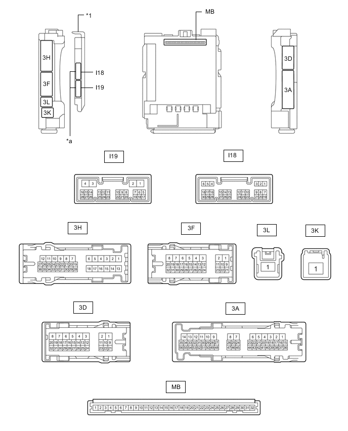
*1 Main Body ECU (Multiplex Network Body ECU) - - *a 2 Connectors - -
-
Remove the main body ECU (multiplex network body ECU) from the instrument panel junction block assembly.
-
Reconnect the instrument panel junction block assembly connectors.
-
Measure the resistance and voltage according to the value(s) in the table below.
Tech Tips
Measure the values on the wire harness side with the connector disconnected.
Terminal No. (Symbol) Wiring Color Terminal Description Condition Specified Condition MB-11 (GND1) - Body ground - Ground Always Below 1 Ω MB-31 (BECU) - Body ground - Auxiliary battery power supply Power switch off 11 to 14 V MB-30 (ACC) - Body ground - Ignition power supply (ACC signal) Power switch on (ACC) 11 to 14 V MB-30 (ACC) - Body ground - Ignition power supply (ACC signal) Power switch off Below 1 V MB-32 (IG) - Body ground - Ignition power supply (IG signal) Power switch on (IG) 11 to 14 V MB-32 (IG) - Body ground - Ignition power supply (IG signal) Power switch off Below 1 V -
Install the main body ECU (multiplex network body ECU) to instrument panel junction block assembly.
-
Measure the voltage according to the value(s) in the table below.
Terminal No. (Symbol) Wiring Color Terminal Description Condition Specified Condition I19-14 (RET) - Body ground L - Body ground*1
B - Body ground*2
Power retract mirror motor drive voltage Mirror retract switch on outer mirror switch assembly retracted position. Below 1 V Mirror retract switch on outer mirror switch assembly driving position. 11 to 14 V I19-15 (AMR) - Body ground P - Body ground Power retract mirror motor drive voltage Mirror retract switch on outer mirror switch assembly auto retracted position. Below 1 V Mirror retract switch on outer mirror switch assembly driving position. 11 to 14 V I19-19 (RETR) - Body ground L - Body ground Power retract mirror motor drive voltage Outer rear view mirror assembly moves to the retracted position. Below 1 V Outer rear view mirror assembly not move. 11 to 14 V I19-20 (RTRR) - Body ground R - Body ground Power retract mirror motor drive voltage Outer rear view mirror assembly moves to the driving position. Below 1 V Outer rear view mirror assembly not move. 11 to 14 V
-
*1: for LHD
-
*2: for RHD
-
-
-
CHECK AIR CONDITIONING AMPLIFIER ASSEMBLY
-
CHECK AIR CONDITIONING CONTROL ASSEMBLY