WINDOW DEFOGGER SYSTEM Rear Window Defogger System does not Operate
DESCRIPTION
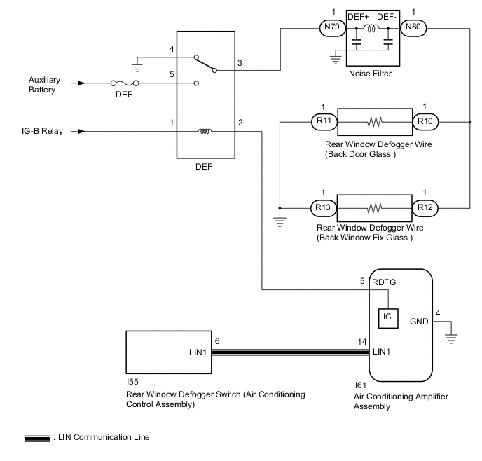
When the rear window defogger switch on the air conditioning control assembly is pressed, the operation signal is transmitted to the air conditioning amplifier assembly via LIN communication. When the air conditioning amplifier assembly receives the signal, it turns on the DEF relay to operate the window defogger system.
WIRING DIAGRAM
CAUTION / NOTICE / HINT
Note
-
Inspect the fuses for circuits related to this system before performing the following procedure.
-
If the auxiliary battery voltage is low, the window defogger system may not operate due to operation of auxiliary battery load control, check the Data List item "Battery Control Count (Body ECU)".
PROCEDURE
-
CHECK REAR WINDOW DEFOGGER SYSTEM
-
Active the rear window defogger system and check the symptoms.
Result Result Proceed to Both rear window defogger wire (back door glass) and rear window defogger wire (back window fix glass) do not warm up A The rear window defogger wire (back door glass) does not warm up B The rear window defogger wire (back window fix glass) does not warm up C
B 
CHECK HARNESS AND CONNECTOR (REAR WINDOW DEFOGGER WIRE (BACK DOOR GLASS) - DEF RELAY AND BODY GROUND) Click here
C
CHECK HARNESS AND CONNECTOR (REAR WINDOW DEFOGGER WIRE (BACK WINDOW FIX GLASS) - DEF RELAY AND BODY GROUND) Click here
A 
-
-
CHECK AIR CONDITIONING SYSTEM
-
Check the air conditioning system.
Tech Tips
Both the window defogger system operation signal and air conditioning system operation signal are transmitted to the air conditioning amplifier assembly via the same communication line.
OK The air conditioning system operates normally. Result Proceed to OK NG
NG 
GO TO AIR CONDITIONING SYSTEM Click here
OK
-
-
PERFORM ACTIVE TEST USING GTS
-
Connect the GTS to the DLC3.
-
Turn the power switch on (IG).
-
Turn the GTS on.
-
Enter the following menus: Body Electrical / Air Conditioner / Active Test.
-
Perform the Active Test according to the display on the GTS.
Body Electrical > Air Conditioner > Active TestTester Display Measurement Item Control Range Diagnostic Note Defogger Relay (Rear) Rear window defogger wire (Back door glass) and Rear window defogger wire (Back window fix glass) OFF or ON -
Body Electrical > Air Conditioner > Active TestTester Display Defogger Relay (Rear) OK The window defogger system operates normally. Result Proceed to OK NG
NG
INSPECT DEF RELAY Click here
OK
-
-
REPLACE AIR CONDITIONING CONTROL ASSEMBLY
-
Replace the air conditioning control assembly with a new or known good one.
-
Check that the window defogger system operates normally.
OK The window defogger system operates normally. Result Proceed to OK NG
OK
END (AIR CONDITIONING CONTROL ASSEMBLY WAS DEFECTIVE)
NG
REPLACE AIR CONDITIONING AMPLIFIER ASSEMBLY Click here
-
-
INSPECT DEF RELAY
-
Inspect the DEF relay.
Result Proceed to OK NG
NG
REPLACE DEF RELAY
OK
-
-
CHECK HARNESS AND CONNECTOR (DEF RELAY - IG-B RELAY AND AUXILIARY BATTERY)
-
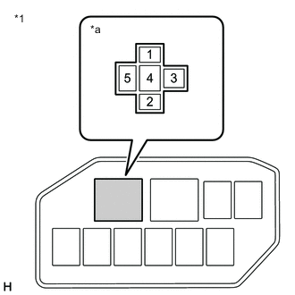
*1 No. 2 Engine Room Relay Block and No. 2 Junction Block Assembly *a DEF Relay Holder Remove the DEF relay from the No. 2 engine room relay block and No. 2 junction block assembly.
-
Measure the voltage according to the value(s) in the table below.
Standard Voltage Tester Connection Condition Specified Condition DEF relay holder terminal-1 - Body ground Power switch on (IG) 11 to 14 V DEF relay holder terminal-5 - Body ground Power switch off 11 to 14 V Result Proceed to OK NG
NG
REPAIR OR REPLACE HARNESS OR CONNECTOR
OK
-
-
CHECK HARNESS AND CONNECTOR (DEF RELAY - AIR CONDITIONING AMPLIFIER ASSEMBLY)
-
*1 No. 2 Engine Room Relay Block and No. 2 Junction Block Assembly *a DEF Relay Holder Remove the DEF relay from the No. 2 engine room relay block and No. 2 junction block assembly.
-
Disconnect the I61 air conditioning amplifier assembly connector.
-
Measure the resistance according to the value(s) in the table below.
Standard Resistance Tester Connection Condition Specified Condition DEF relay holder terminal-2 - I61-5 (RDFG) Always Below 1 Ω DEF relay holder terminal-2 or I61-5 (RDFG) - Body ground Always 10 kΩ or higher Result Proceed to OK NG
NG
REPAIR OR REPLACE HARNESS OR CONNECTOR
OK
-
-
CHECK AIR CONDITIONING AMPLIFIER ASSEMBLY
-
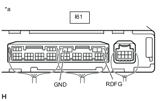
*a Component with harness connected
(Air Conditioning Amplifier Assembly)
Reconnect the I61 air conditioning amplifier assembly connector.
-
Reinstall the DEF relay.
-
Remove the air conditioning amplifier assembly with its connectors still connected.
-
Measure the voltage according to the value(s) in the table below.
Standard Voltage Tester Connection Condition Specified Condition I61-5 (RDFG) - I61-4 (GND) Power switch on (IG), rear window defogger switch on Below 1 V I61-5 (RDFG) - I61-4 (GND) Power switch on (IG), rear window defogger switch off 11 to 14 V Result Proceed to OK NG
NG
REPLACE AIR CONDITIONING AMPLIFIER ASSEMBLY Click here
OK
-
-
INSPECT NOISE FILTER
-
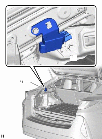
*1 Noise Filter Remove the noise filter.
-
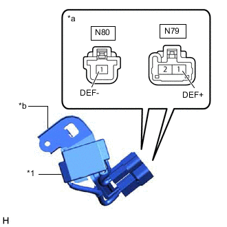
*1 Noise Filter *a Component without harness connected
(Noise Filter)
*b Noise Filter Body Inspect the noise filter.
-
Measure the resistance according to the value(s) in the table below.
Standard Resistance Tester Connection Condition Specified Condition N79-1 (DEF+) - N80-1 (DEF-) Noise filter temperature 20 °C (68 °F) Below 0.001 Ω N79-1 (DEF+) - Noise filter body Noise filter temperature 20 °C (68 °F) No Continuity N80-1 (DEF-) - Noise filter body Noise filter temperature 20 °C (68 °F) No Continuity
Result Proceed to OK NG -
NG
REPLACE NOISE FILTER
OK
-
-
CHECK HARNESS AND CONNECTOR (DEF RELAY - NOISE FILTER)
-
*1 No. 2 Engine Room Relay Block and No. 2 Junction Block Assembly *a DEF Relay Holder Remove the DEF relay from the No. 2 engine room relay block and No. 2 junction block assembly.
-
Disconnect the N79 noise filter connector.
-
Measure the resistance according to the value(s) in the table below.
Standard Resistance Tester Connection Condition Specified Condition DEF relay holder terminal-3 - N79-1 (DEF+) Always Below 1 Ω DEF relay holder terminal-3 or N79-1 (DEF+) - Body ground Always 10 kΩ or higher Result Proceed to OK NG
NG
REPAIR OR REPLACE HARNESS OR CONNECTOR
OK
-
-
CHECK HARNESS AND CONNECTOR (REAR WINDOW DEFOGGER WIRE (BACK DOOR GLASS) AND REAR WINDOW DEFOGGER WIRE (BACK WINDOW FIX GLASS) - NOISE FILTER AND BODY GROUND))
-
Disconnect the N80 noise filter connector.
-
Disconnect the R10, R11, R12 and R13 rear window defogger wire (back door glass) and rear window defogger wire (back window fix glass) connectors.
-
Measure the resistance according to the value(s) in the table below.
Standard Resistance Tester Connection Condition Specified Condition R10-1 - N80-1 (DEF-) Always Below 1 Ω R12-1 - N80-1 (DEF-) Always Below 1 Ω R10-1, R12-1 or N80-1 (DEF-) - Body ground Always 10 kΩ or higher R11-1 - Body ground Always Below 1 Ω R13-1 - Body ground Always Below 1 Ω Result Proceed to OK NG
OK
USE SIMULATION METHOD TO CHECK Click here
NG
REPAIR OR REPLACE HARNESS OR CONNECTOR
-
-
CHECK HARNESS AND CONNECTOR (REAR WINDOW DEFOGGER WIRE (BACK DOOR GLASS) - DEF RELAY AND BODY GROUND)
-
Disconnect the N80 noise filter connector.
-
Disconnect the R10 and R11 rear window defogger wire (back door glass) connectors.
-
Measure the resistance according to the value(s) in the table below.
Standard Resistance Tester Connection Condition Specified Condition R10-1 - N80-1 (DEF-) Always Below 1 Ω R10-1 or N80-1 (DEF-) - Body ground Always 10 kΩ or higher R11-1 - Body ground Always Below 1 Ω Result Proceed to OK NG
OK
REPAIR OR REPLACE REAR WINDOW DEFOGGER WIRE (BACK DOOR GLASS) Click here
NG
REPAIR OR REPLACE HARNESS OR CONNECTOR
-
-
CHECK HARNESS AND CONNECTOR (REAR WINDOW DEFOGGER WIRE (BACK WINDOW FIX GLASS) - DEF RELAY AND BODY GROUND)
-
Disconnect the N80 noise filter connector.
-
Disconnect the R12 and R13 rear window defogger wire (back window fix glass) connectors.
-
Measure the resistance according to the value(s) in the table below.
Standard Resistance Tester Connection Condition Specified Condition R12-1 - N80-1 (DEF-) Always Below 1 Ω R12-1 or N80-1 (DEF-) - Body ground Always 10 kΩ or higher R13-1 - Body ground Always Below 1 Ω Result Proceed to OK NG
OK
REPAIR OR REPLACE REAR WINDOW DEFOGGER WIRE (BACK WINDOW FIX GLASS) Click here
NG
REPAIR OR REPLACE HARNESS OR CONNECTOR
-