FUEL LID OPENER SYSTEM Fuel Lid Opener does not Operate
DESCRIPTION
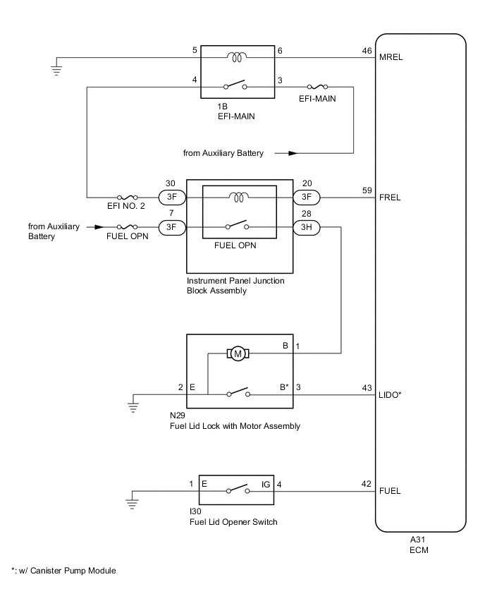
When the fuel lid opener switch is pushed, a fuel lid opener switch signal is sent to the ECM. The ECM turns on the FUEL OPN relay and the fuel lid lock with motor assembly opens the fuel lid. When the fuel lid is open, a fuel lid courtesy switch signal is output from the fuel lid lock with motor assembly.
WIRING DIAGRAM
CAUTION / NOTICE / HINT
Note
Inspect the fuses for circuits related to this system before performing the following procedure.
PROCEDURE
-
CHECK FOR DTC (SFI SYSTEM)
-
Connect the GTS to the DLC3.
-
Turn the power switch on (IG).
-
Turn the GTS on.
-
Enter the following menus: Powertrain / Engine / Trouble Codes.
Powertrain > Engine > Trouble CodesOK SFI system DTCs are not output. Result Result Proceed to OK A NG (w/ Canister Pump Module) B NG (w/o Canister Pump Module) C
B 
GO TO SFI SYSTEM Click here
C
GO TO SFI SYSTEM Click here
A 
-
-
CONFIRM MODEL
-
Choose the model to be inspected.
Result Result Proceed to w/ Canister Pump Module A w/o Canister Pump Module B
B 
READ VALUE USING GTS (Fuel Lid SW) Click here
A
-
-
PERFORM ACTIVE TEST USING GTS (Activate the Fuel Filler Opener)
-
Enter the following menus: Powertrain / Engine / Active Test.
-
Perform the Active Test according to the display on the GTS.
Powertrain > Engine > Active TestTester Display Measurement Item Control Range Diagnostic Note Activate the Fuel Filler Opener Fuel lid lock with motor assembly OFF or ON -
Powertrain > Engine > Active TestTester Display Activate the Fuel Filler Opener OK The fuel lid lock with motor assembly operates normally. Result Proceed to OK NG
NG
INSPECT FUEL LID LOCK WITH MOTOR ASSEMBLY Click here
OK
-
-
READ VALUE USING GTS (Fuel Lid SW)
-
Enter the following menus: Powertrain / Engine / Data List.
-
Read the Data List according to the display on the GTS.
Powertrain > Engine > Data ListTester Display Measurement Item Range Normal Condition Diagnostic Note Fuel Lid SW Fuel lid opener switch status Close or Open Close: Fuel lid opener switch not pushed
Open: Fuel lid opener switch pushed
-
Powertrain > Engine > Data ListTester Display Fuel Lid SW OK The GTS display changes correctly in response to the operation of the fuel lid opener switch. Result Proceed to OK NG
NG
INSPECT FUEL LID OPENER SWITCH Click here
OK
-
-
READ VALUE USING GTS (Fuel Lid Sensor SW)
-
Enter the following menus: Powertrain / Engine / Data List.
-
Read the Data List according to the display on the GTS.
Powertrain > Engine > Data ListTester Display Measurement Item Range Normal Condition Diagnostic Note Fuel Lid Sensor SW Fuel lid courtesy switch status Close or Open Close: Fuel lid closed
Open: Fuel lid open
-
Powertrain > Engine > Data ListTester Display Fuel Lid Sensor SW OK The GTS display changes correctly in response to the operation of the fuel lid courtesy switch (fuel lid lock with motor assembly). Result Proceed to OK NG
OK
REPLACE ECM Click here
NG
-
-
INSPECT FUEL LID LOCK WITH MOTOR ASSEMBLY
-
Remove the fuel lid lock with motor assembly.
-
Inspect the fuel lid lock with motor assembly (fuel lid courtesy switch).
Result Proceed to OK NG
NG
REPLACE FUEL LID LOCK WITH MOTOR ASSEMBLY Click here
OK
-
-
CHECK HARNESS AND CONNECTOR (FUEL LID LOCK WITH MOTOR ASSEMBLY - ECM)
-
Disconnect the A31 ECM connector.
-
Measure the resistance according to the value(s) in the table below.
Standard Resistance Tester Connection Condition Specified Condition N29-3 (B) - A31-43 (LIDO) Always Below 1 Ω N29-3 (B) or A31-43 (LIDO) - Body ground Always 10 kΩ or higher Result Proceed to OK NG
OK
REPLACE ECM Click here
NG
REPAIR OR REPLACE HARNESS OR CONNECTOR
-
-
INSPECT FUEL LID OPENER SWITCH
-
Remove the fuel lid opener switch.
-
Inspect the fuel lid opener switch.
Result Proceed to OK NG
NG
REPLACE FUEL LID OPENER SWITCH Click here
OK
-
-
CHECK HARNESS AND CONNECTOR (FUEL LID OPENER SWITCH - ECM AND BODY GROUND)
-
Disconnect the A31 ECM connector.
-
Measure the resistance according to the value(s) in the table below.
Standard Resistance Tester Connection Condition Specified Condition I30-4 (IG) - A31-42 (FUEL) Always Below 1 Ω I30-1 (E) - Body ground Always Below 1 Ω I30-4 (IG) or A31-42 (FUEL) - Body ground Always 10 kΩ or higher Result Proceed to OK NG
OK
REPLACE ECM Click here
NG
REPAIR OR REPLACE HARNESS OR CONNECTOR
-
-
INSPECT FUEL LID LOCK WITH MOTOR ASSEMBLY
-
Remove the fuel lid lock with motor assembly.
Click here
-
Inspect the fuel lid lock with motor assembly (motor operation).
Result Proceed to OK NG
NG
REPLACE FUEL LID LOCK WITH MOTOR ASSEMBLY Click here
OK
-
-
CHECK HARNESS AND CONNECTOR (INSTRUMENT PANEL JUNCTION BLOCK ASSEMBLY - AUXILIARY BATTERY)
-
Disconnect the 3F instrument panel junction block assembly connector.
-

*a Front view of wire harness connector
(to Instrument Panel Junction Block Assembly)
Measure the voltage according to the value(s) in the table below.
Standard Voltage Tester Connection Condition Specified Condition 3F-7 - Body ground Power switch off 11 to 14 V 3F-30 - Body ground Power switch on (IG) 11 to 14 V Power switch off and fuel lid opener switch not pressed → fuel lid opener switch pressed Below 1 V → 11 to 14 V Result Result Proceed to OK A The result for terminal 3F-7 is not as specified. B The result for terminal 3F-30 (with power switch on (IG)) is not as specified. The result for terminal 3F-30 (with power switch off and fuel lid opener switch pressed) is not as specified. C
B
REPAIR OR REPLACE HARNESS OR CONNECTOR
C
REPLACE ECM Click here
A
-
-
CHECK HARNESS AND CONNECTOR (INSTRUMENT PANEL JUNCTION BLOCK ASSEMBLY - ECM)
-
Disconnect the A31 ECM connector.
-
Measure the resistance according to the value(s) in the table below.
Standard Resistance Tester Connection Condition Specified Condition 3F-20 - A31-59 (FREL) Always Below 1 Ω 3F-20 or A31-59 (FREL) - Body ground Always 10 kΩ or higher Result Proceed to OK NG
NG
REPAIR OR REPLACE HARNESS OR CONNECTOR
OK
-
-
CHECK HARNESS AND CONNECTOR (INSTRUMENT PANEL JUNCTION BLOCK ASSEMBLY - FUEL LID LOCK WITH MOTOR ASSEMBLY)
-
Disconnect the 3H instrument panel junction block assembly connector.
-
Measure the resistance according to the value(s) in the table below.
Standard Resistance Tester Connection Condition Specified Condition 3H-28 - N29-1 (B) Always Below 1 Ω 3H-28 or N29-1 (B) - Body ground Always 10 kΩ or higher Result Proceed to OK NG
NG
REPAIR OR REPLACE HARNESS OR CONNECTOR
OK
-
-
REPLACE INSTRUMENT PANEL JUNCTION BLOCK ASSEMBLY
-
Replace the instrument panel junction block assembly.
Result Proceed to NEXT
NEXT
-
-
CHECK FUEL LID OPEN OPERATION
-
Check that the fuel lid can be opened.
OK The fuel lid can be opened. Result Proceed to OK NG
OK
END (INSTRUMENT PANEL JUNCTION BLOCK ASSEMBLY WAS DEFECTIVE)
NG
REPLACE ECM Click here
-
-
READ VALUE USING GTS (Fuel Lid SW)
-
Enter the following menus: Powertrain / Engine / Data List.
-
Read the Data List according to the display on the GTS.
Powertrain > Engine > Data ListTester Display Measurement Item Range Normal Condition Diagnostic Note Fuel Lid SW Fuel lid opener switch status Close or Open Close: Fuel lid opener switch not pushed
Open: Fuel lid opener switch pushed
-
Powertrain > Engine > Data ListTester Display Fuel Lid SW OK The GTS display changes correctly in response to the operation of the fuel lid opener switch. Result Proceed to OK NG
NG
CHECK HARNESS AND CONNECTOR (FUEL LID OPENER SWITCH - ECM AND BODY GROUND) Click here
OK
-
-
INSPECT FUEL LID LOCK WITH MOTOR ASSEMBLY
-
Remove the fuel lid lock with motor assembly.
-
Inspect the fuel lid lock with motor assembly.
Result Proceed to OK NG
NG
REPLACE FUEL LID LOCK WITH MOTOR ASSEMBLY Click here
OK
-
-
CHECK HARNESS AND CONNECTOR (FUEL LID LOCK WITH MOTOR ASSEMBLY - BODY GROUND)
-
Measure the resistance according to the value(s) in the table below.
Standard Resistance Tester Connection Condition Specified Condition N29-2 (E) - Body ground Always 10 kΩ or higher Result Proceed to OK NG
NG
REPAIR OR REPLACE HARNESS OR CONNECTOR
OK
-
-
CHECK HARNESS AND CONNECTOR (INSTRUMENT PANEL JUNCTION BLOCK ASSEMBLY - FUEL LID LOCK WITH MOTOR ASSEMBLY)
-
Disconnect the 3H instrument panel junction block assembly connector.
-
Measure the resistance according to the value(s) in the table below.
Standard Resistance Tester Connection Condition Specified Condition 3H-28 - N29-1 (B) Always Below 1 Ω 3H-28 or N29-1 (B) - Body ground Always 10 kΩ or higher Result Proceed to OK NG
NG
REPAIR OR REPLACE HARNESS OR CONNECTOR
OK
-
-
CHECK HARNESS AND CONNECTOR (INSTRUMENT PANEL JUNCTION BLOCK ASSEMBLY - AUXILIARY BATTERY)
-
Disconnect the 3F instrument panel junction block assembly connector.
-
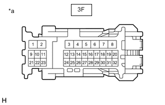
*a Front view of wire harness connector
(to Instrument Panel Junction Block Assembly)
Measure the voltage according to the value(s) in the table below.
Standard Voltage Tester Connection Condition Specified Condition 3F-7 - Body ground Power switch off 11 to 14 V 3F-30 - Body ground Power switch on (IG) 11 to 14 V Power switch off and fuel lid opener switch not pressed → fuel lid opener switch pressed Below 1 V → 11 to 14 V Result Result Proceed to OK A The result for terminal 3F-7 is not as specified. B The result for terminal 3F-30 (with power switch on (IG)) is not as specified. The result for terminal 3F-30 (with power switch off and fuel lid opener switch pressed) is not as specified. C
B
REPAIR OR REPLACE HARNESS OR CONNECTOR
C
REPLACE ECM Click here
A
-
-
CHECK HARNESS AND CONNECTOR (INSTRUMENT PANEL JUNCTION BLOCK ASSEMBLY - ECM)
-
Disconnect the A31 ECM connector.
-
Measure the resistance according to the value(s) in the table below.
Standard Resistance Tester Connection Condition Specified Condition 3F-20 - A31-59 (FREL) Always Below 1 Ω 3F-20 or A31-59(FREL) - Body ground Always 10 kΩ or higher Result Proceed to OK NG
NG
REPAIR OR REPLACE HARNESS OR CONNECTOR
OK
-
-
REPLACE INSTRUMENT PANEL JUNCTION BLOCK ASSEMBLY
-
Replace the instrument panel junction block assembly.
Result Proceed to NEXT
NEXT
-
-
CHECK FUEL LID OPEN OPERATION
-
Check that the fuel lid can be opened.
OK The fuel lid can be opened. Result Proceed to OK NG
OK
END (INSTRUMENT PANEL JUNCTION BLOCK ASSEMBLY WAS DEFECTIVE)
NG
REPLACE ECM Click here
-
-
CHECK HARNESS AND CONNECTOR (FUEL LID OPENER SWITCH - ECM AND BODY GROUND)
-
Disconnect the I30 fuel lid opener switch connector.
-
Disconnect the A31 ECM connector.
-
Measure the resistance according to the value(s) in the table below.
Standard Resistance Tester Connection Condition Specified Condition I30-4 (IG) - A31-42(FUEL) Always Below 1 Ω I30-4 (IG) or A31-42 (FUEL) - Body ground Always 10 kΩ or higher I30-1 (E) - Body ground Always Below 1 Ω Result Proceed to OK NG
OK
REPLACE FUEL LID OPENER SWITCH Click here
NG
REPAIR OR REPLACE HARNESS OR CONNECTOR
-