ROOF HEADLINING INSTALLATION
PROCEDURE
-
INSTALL ROOF HEADLINING ASSEMBLY
-
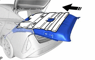

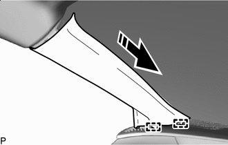
Install in this Direction Put the roof headlining assembly back into the vehicle through the back door as shown in the illustration.
Note
Do not damage the roof headlining assembly or vehicle interior.
-
Install the roof headlining assembly with the 3 clips.
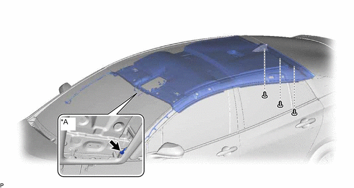
*A w/ Digital Audio Broadcasting Antenna - - -
w/ Digital Audio Broadcasting Antenna:
-
Connect the connector.
-
-
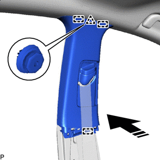
for Rear Pillar RH Side:
-
Connect the 2 connectors.
-
-
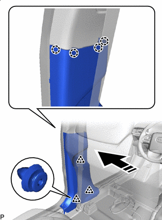
for Front Pillar LH Side:
-
Remove the protective cover.
-
Connect the 2 connectors.
-
Engage the 4 clamps.
-
Install the protective cover.
-
-
for Front Pillar RH Side:
-
Remove the protective cover.
-
Connect each connector.
-
Engage the 3 clamps.
-
Install the protective cover.
-
-
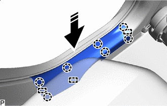
for Windshield Glass Side:
-
Connect each connector.
-
-
-
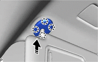
INSTALL VISOR HOLDER LH
-
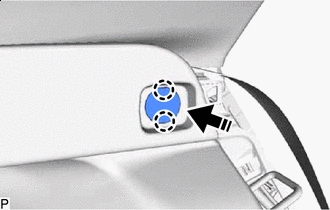
Engage the 2 claws.
-
Install in this Direction Push in the visor holder LH as shown in the illustration.
-
-
INSTALL VISOR ASSEMBLY LH
-
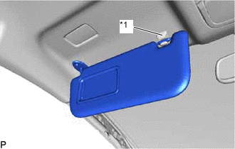
*1 Visor Holder LH Connect the visor assembly LH to the visor holder LH.
-
for "TORX" Screw:
-
Using a T25 "TORX" socket wrench, install the visor assembly LH with the 2 screws.
-
-
except "TORX" Screw:
-
Install the visor assembly LH with the 2 screws.
-
-
-
INSTALL VISOR BRACKET COVER (for LH Side)
-
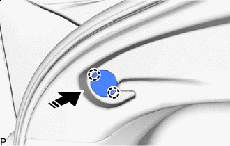
Install in this Direction Engage the 4 claws to install the visor bracket cover as shown in the illustration.
-
-
INSTALL VISOR HOLDER RH
Tech Tips
Use the same procedure as for the LH side.
-
INSTALL VISOR ASSEMBLY RH
Tech Tips
Use the same procedure as for the LH side.
-
INSTALL VISOR BRACKET COVER (for RH Side)
Tech Tips
Use the same procedure as for the LH side.
-
INSTALL ASSIST GRIP ASSEMBLY
Tech Tips
Use the same procedure for the RH side and LH side.
-
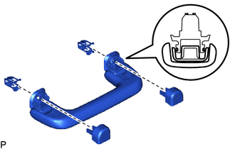
Install the 2 clips to the assist grip.
-
Temporarily install the 2 assist grip covers to the assist grip as shown in the illustration.
-
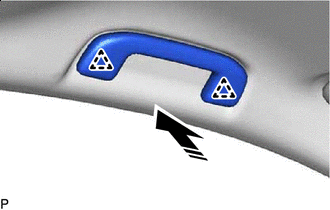
Install in this Direction Engage the 2 clips to install the assist grip assembly as shown in the illustration.
-
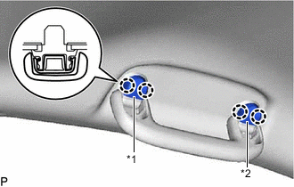
*1 assist grip cover LH *2 assist grip cover RH Engage the 4 claws to install the assist grip cover LH and assist grip cover RH.
Note
Make sure that the clip is engaged securely.
-
-
INSTALL REAR ASSIST GRIP ASSEMBLY LH
Tech Tips
Use the same procedure as for the assist grip assembly.
-
INSTALL REAR ASSIST GRIP ASSEMBLY RH
Tech Tips
Use the same procedure as for the assist grip assembly.
-
INSTALL NO. 1 FORWARD RECOGNITION COVER
-
INSTALL NO. 2 FORWARD RECOGNITION COVER
-
INSTALL INNER REAR VIEW MIRROR STAY HOLDER COVER (w/ Cover)
-
INSTALL AIR CONDITIONING THERMISTOR ASSEMBLY (w/ Humidity Sensor)
-
INSTALL SENSOR COVER (w/ Humidity Sensor)
-
INSTALL RAIN SENSOR (w/ Rain Sensor)
-
INSTALL RAIN SENSOR COVER (w/ Rain Sensor)
-
INSTALL NO. 1 ROOM LIGHT ASSEMBLY
-
INSTALL ROOF CONSOLE BOX ASSEMBLY
-
INSTALL ROOF SIDE INNER GARNISH ASSEMBLY LH
-
Engage the 5 clips to install the roof side inner garnish assembly LH as shown in the illustration.
Install in this Direction - -
-
-
INSTALL DECK TRIM SIDE PANEL ASSEMBLY LH
-
When reusing the deck trim side panel assembly LH:
-
*1 No. 2 Luggage Compartment Trim Hook Turn in this Direction (1) 
Remove in this Direction (2) Remove the clip from the No. 2 luggage compartment trim hook as shown in the illustration.
-
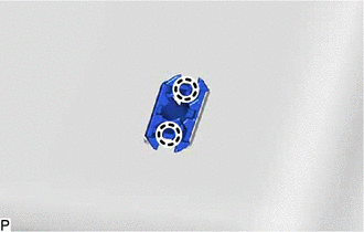
*1 Clip Piece 
Insert Screwdriver Here Insert in this Direction Using a screwdriver, push out the clip piece.
Tech Tips
Make sure that the clip piece are positioned as shown in the illustration.
-
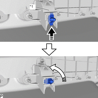
*1 No. 2 Luggage Compartment Trim Hook Install in this Direction (1) Turn in this Direction (2) Install the clip to the No. 2 luggage compartment trim hook as shown in the illustration.
-
-
Engage the guide, 5 claws and 3 clips.
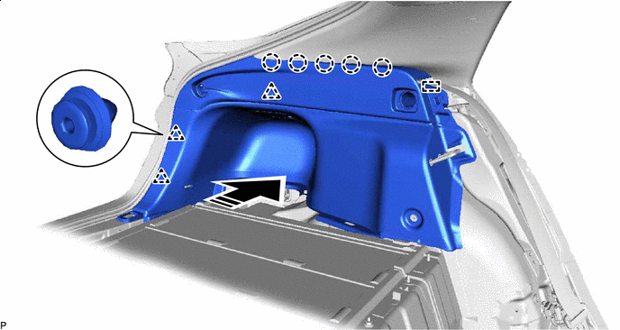
Install in this Direction - - -
Engage the clip.
-
Install the deck trim side panel assembly LH with the 2 screws.
-
-
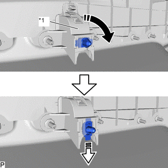
INSTALL ROPE HOOK (for LH Side without Toyota Safety Sense)
-
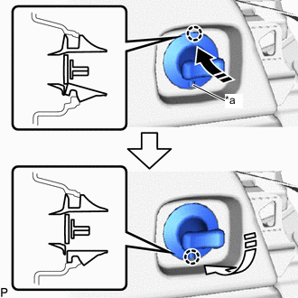
*a Notch Install in this Direction (1) Install in this Direction (2) With the notch of the rope hook facing downward, push the rope hook in the direction indicated by the arrow (1) shown in the illustration to engage the claw.
-
Turn the rope hook in the direction indicated by the arrow (2) to engage the claw and install it.
-
-
INSTALL NO. 2 ROPE HOOK (for LH Side without Toyota Safety Sense)
-
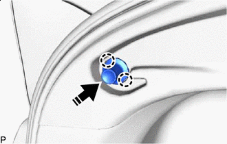
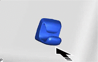
Install in this Direction Engage the 2 claws to install the No. 2 rope hook as shown in the illustration.
-
-
INSTALL NO. 1 TONNEAU COVER HOLDER CAP (for LH Side with Toyota Safety Sense)
-
Install in this Direction Engage the 2 claws to install the No. 1 tonneau cover holder cap as shown in the illustration.
-
-
INSTALL TONNEAU COVER HOOK A (for LH Side with Toyota Safety Sense)
-
Install in this Direction Engage the 2 claws to install the tonneau cover hook A as shown in the illustration.
-
-
INSTALL REAR SEAT SIDE GARNISH LH
-
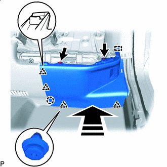
Install in this Direction Engage the 2 guides, claw and 2 clips to install the rear seat side garnish LH as shown in the illustration.
-
-
INSTALL REAR SEATBACK HINGE SUB-ASSEMBLY LH
-
Install the rear seatback hinge sub-assembly LH with the bolt.
- Torque:
- 18 N*m { 184 kgf*cm, 13 ft.*lbf }
-
-
INSTALL REAR UNDER SIDE COVER LH
-
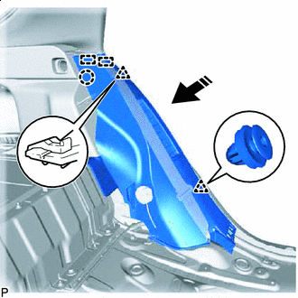
Install in this Direction Engage the guide, claw and 4 clips as shown in the illustration.
-
Install the rear under side cover LH with the 2 clips.
-
-
INSTALL ROOF SIDE INNER GARNISH ASSEMBLY RH
Tech Tips
Use the same procedure as for the LH side.
-
INSTALL NO. 1 LUGGAGE COMPARTMENT LIGHT ASSEMBLY
-
INSTALL DECK TRIM SIDE PANEL ASSEMBLY RH
Tech Tips
Use the same procedure as for the LH side.
-
INSTALL ROPE HOOK (for RH Side without Toyota Safety Sense)
Tech Tips
Use the same procedure as for the LH side.
-
INSTALL NO. 2 ROPE HOOK (for RH Side without Toyota Safety Sense)
Tech Tips
Use the same procedure as for the LH side.
-
INSTALL NO. 1 TONNEAU COVER HOLDER CAP (for RH Side with Toyota Safety Sense)
Tech Tips
Use the same procedure as for the LH side.
-
INSTALL TONNEAU COVER HOOK A (for RH Side with Toyota Safety Sense)
Tech Tips
Use the same procedure as for the LH side.
-
INSTALL REAR SEAT SIDE GARNISH RH
Tech Tips
Use the same procedure as for the LH side.
-
INSTALL REAR SEATBACK HINGE SUB-ASSEMBLY RH
Tech Tips
Use the same procedure as for the LH side.
-
INSTALL REAR UNDER SIDE COVER RH
Tech Tips
Use the same procedure as for the LH side.
-
INSTALL REAR SEAT ASSEMBLY
-
INSTALL CENTER PILLAR GARNISH ASSEMBLY LH
-
Install in this Direction Engage the 3 guides and clip as shown in the illustration.
-
Install the center pillar garnish assembly LH with the 2 clips.
-
-
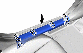
INSTALL LOWER CENTER PILLAR GARNISH LH
-
Install in this Direction Engage the 4 claws and 3 clips to install the lower center pillar garnish LH as shown in the illustration.
-
-
CONNECT FRONT SEAT OUTER BELT ASSEMBLY LH
-
INSTALL LAP BELT OUTER ANCHOR COVER (for LH Side)
-
INSTALL REAR DOOR OPENING TRIM WEATHERSTRIP LH
-
INSTALL REAR DOOR SCUFF PLATE LH
-
Install in this Direction Engage the 3 guides and 7 claws to install the rear door scuff plate LH as shown in the illustration.
-
-
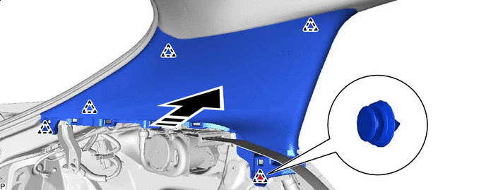
INSTALL FRONT PILLAR GARNISH LH
-
Remove the protective cover.
-
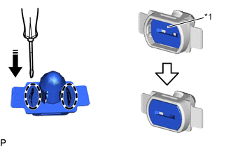
Engage the front pillar garnish clip to the front pillar garnish LH.
Note
If the installation hole for the front pillar garnish clip on the front pillar garnish LH is damaged or deformed, replace the front pillar garnish LH and front pillar garnish clip with new ones.
Tech Tips
Make sure that the notch of the front pillar garnish clip is touching the protrusion of front pillar garnish LH.
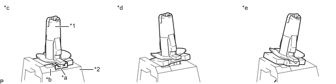
*1 Front Pillar Garnish Clip *2 Front Pillar Garnish LH *a Notch *b Protrusion *c OK *d NG (Incorrect orientation) *e NG (Overlapping) - - -
Install in this Direction Push the front pillar garnish LH as shown in the illustration to engage the 2 guides.
-
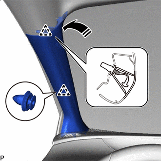
Install in this Direction Engage the clip and front pillar garnish clip to install the front pillar garnish LH as shown in the illustration.
Tech Tips
Make sure that the curtain shield airbag assembly LH is not pinched.
-
-
INSTALL FRONT DOOR OPENING TRIM WEATHERSTRIP LH
-
INSTALL COWL SIDE TRIM BOARD LH
-
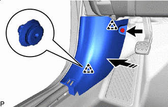
Install in this Direction Engage the 2 clips as shown in the illustration.
-
Install the cowl side trim board LH with the clip.
-
-
INSTALL FRONT DOOR SCUFF PLATE LH
-
Install in this Direction Engage the 2 guides and 8 claws to install the front door scuff plate LH as shown in the illustration.
-
-
INSTALL CENTER PILLAR GARNISH ASSEMBLY RH
Tech Tips
Use the same procedure as for the LH side.
-
INSTALL LOWER CENTER PILLAR GARNISH RH
Tech Tips
Use the same procedure as for the LH side.
-
CONNECT FRONT SEAT OUTER BELT ASSEMBLY RH
Tech Tips
Use the same procedure as for the LH side.
-
INSTALL LAP BELT OUTER ANCHOR COVER (for RH Side)
Tech Tips
Use the same procedure as for the LH side.
-
INSTALL REAR DOOR OPENING TRIM WEATHERSTRIP RH
Tech Tips
Use the same procedure as for the LH side.
-
INSTALL REAR DOOR SCUFF PLATE RH
Tech Tips
Use the same procedure as for the LH side.
-
INSTALL FRONT PILLAR GARNISH RH
Tech Tips
Use the same procedure as for the LH side.
-
INSTALL FRONT DOOR OPENING TRIM WEATHERSTRIP RH
Tech Tips
Use the same procedure as for the LH side.
-
INSTALL COWL SIDE TRIM BOARD RH
Tech Tips
Use the same procedure as for the LH side.
-
INSTALL FRONT DOOR SCUFF PLATE RH
Tech Tips
Use the same procedure as for the LH side.
-
INSTALL REAR DECK TRIM COVER
-
Engage the 4 clips.
-
Install the rear deck trim cover with the bolt.
- Torque:
- 7.5 N*m { 76 kgf*cm, 66 in.*lbf }
-
-
INSTALL DECK TRIM SERVICE HOLE COVER
-
INSTALL DECK FLOOR BOX RH
-
Engage the 2 claws and 4 guides to install the deck floor box RH.
-
-
INSTALL DECK FLOOR BOX LH
-
Engage the 2 claws and 5 guides to install the deck floor box LH.
-
-
INSTALL REAR NO. 1 FLOOR BOARD
-
Engage the 2 guides.
-
Install the rear No. 1 floor board with the 4 clips.
-
-
INSTALL REAR NO. 3 FLOOR BOARD
-
Install the rear No. 3 floor board.
-
-
INSTALL REAR NO. 4 FLOOR BOARD
-
Install the rear No. 4 floor board.
-
-
INSTALL REAR NO. 2 FLOOR BOARD
-
Install the rear No. 2 floor board.
-
-
INSTALL TONNEAU COVER ASSEMBLY
-
Install the tonneau cover assembly.
-