ROOF HEADLINING REASSEMBLY
PROCEDURE
-
INSTALL NO. 2 ROOF HEADLINING PAD (w/ Roof Headlining Pad)
-
Align the No. 2 roof headlining pad with the markings on the roof headlining assembly and install it using hot-melt glue as shown in the illustration.
*a Hot-melt Glue *b Marking
-
-
INSTALL ROOF HEADLINING PAD (w/ Roof Headlining Pad)
-
Align the roof headlining pad with the markings on the roof headlining assembly and install it using hot-melt glue as shown in the illustration.
*a Hot-melt Glue *b Marking
-
-
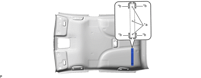
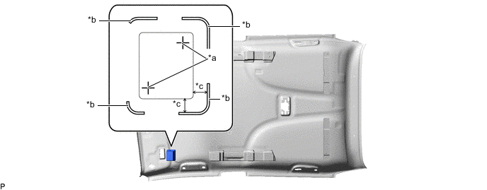
INSTALL NO. 2 ROOF HEADLINING SET PLATE LH (w/ Roof Headlining Pad)
-
Align the No. 2 roof headlining set plate LH with the markings on the roof headlining assembly and install it using hot-melt glue as shown in the illustration.
*a Hot-melt Glue *b Marking
-
-
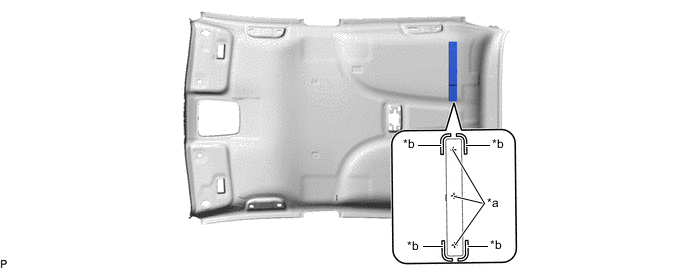
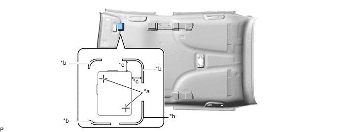
INSTALL NO. 2 ROOF HEADLINING SET PLATE RH (w/ Roof Headlining Pad)
-
Align the No. 2 roof headlining set plate RH with the markings on the roof headlining assembly and install it using hot-melt glue as shown in the illustration.
*a Hot-melt Glue *b Marking
-
-
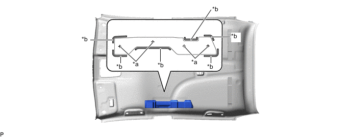
INSTALL FRONT SIDE RAIL SPACER LH (w/ Roof Headlining Pad)
-
Align the front side rail spacer LH with the markings on the roof headlining assembly and install it using hot-melt glue as shown in the illustration.
*a Hot-melt Glue *b Marking *c 5 mm (0.197 in.) - -
-
-
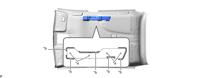
INSTALL FRONT SIDE RAIL SPACER RH (w/ Roof Headlining Pad)
-
Align the front side rail spacer RH with the markings on the roof headlining assembly and install it using hot-melt glue as shown in the illustration.
*a Hot-melt Glue *b Marking *c 5 mm (0.197 in.) - -
-
-
INSTALL NO. 1 ROOF WIRE
-
Apply butyl tape as shown in the illustration.
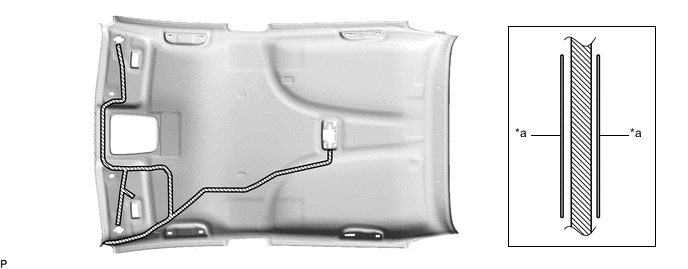
*a Marking - - 
Butyl Tape - - Note
Securely attach the butyl tape.
-
Turn the 2 visor connectors clockwise approximately 90° to install them to the roof headlining assembly.
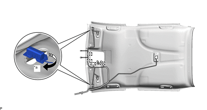
*a 90° - - 
Rotation Direction - - -
Engage the 4 clamps.
-
Align the marking tape (A) on the No. 1 roof wire with the tab on the front side of the roof headlining assembly.
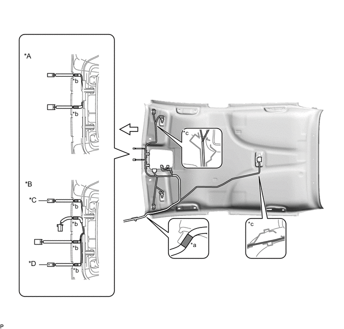
*A w/o Toyota Safety Sense *B w/ Toyota Safety Sense *C for LHD with Rain Sensor *D for RHD with Rain Sensor *a Marking Tape (A) *b Marking Tape (B) *c Adjustment Area - - 
Front - - -
Align the edge of each marking tape (B) on the No. 1 roof wire with each notch on the roof headlining assembly.
-
Attach the No. 1 roof wire with the butyl tape.
Note
-
Securely attach the No. 1 roof wire.
-
If any of the No. 1 roof wire is left loose, it will cause an abnormal noise.
-
Make sure to attach the No. 1 roof wire without leaving any of it loose.
Tech Tips
Secure the extra length of the No. 1 roof wire in the adjustment area.
-
-
Install the No. 1 roof wire to the roof headlining assembly with adhesive tape.
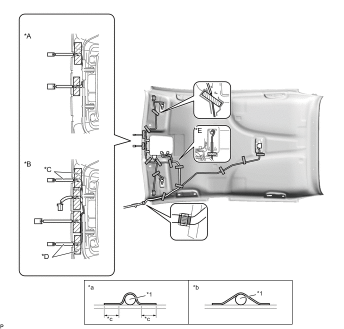
*A w/o Toyota Safety Sense *B w/ Toyota Safety Sense *C for LHD with Rain Sensor *D for RHD with Rain Sensor *E w/ Intrusion Sensor - - *1 No. 1 Roof Wire - - *a Correct *b Incorrect *c 10 mm (0.394 in.) or more - - Adhesive Tape - - Note
-
Apply the tape securely in place.
-
Do not touch the adhesive surface when applying the tape to prevent adhesion failure.
-
-
-
INSTALL THEFT WARNING ULTRASONIC SENSOR (w/ Intrusion Sensor)
-
INSTALL VANITY LIGHT ASSEMBLY
Tech Tips
Use the same procedure for the RH side and LH side.
-
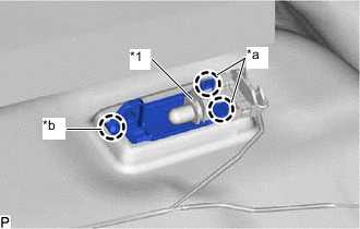
*1 Bulb Holder *a Claw (A) *b Claw (B) Engage the claw (B) to install the vanity light assembly.
-
Engage the 2 claws (A) to install the bulb holder to the vanity light assembly.
-
-
INSTALL NO. 2 ANTENNA CORD SUB-ASSEMBLY
-
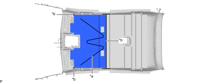
INSTALL NO. 2 ROOF SILENCER PAD
-
Align the No. 2 roof silencer pad with the markings on the roof headlining assembly and install it using hot-melt glue as shown in the illustration.
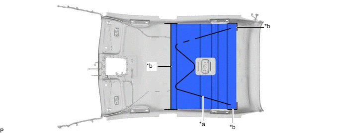
*a Hot-melt Glue *b Marking
-
-
INSTALL NO. 1 ROOF SILENCER PAD
-
Align the No. 1 roof silencer pad with the markings on the roof headlining assembly and install it using hot-melt glue as shown in the illustration.
*a Hot-melt Glue *b Marking
-