LOWER INSTRUMENT PANEL REMOVAL
CAUTION / NOTICE / HINT
The necessary procedures (adjustment, calibration, initialization or registration) that must be performed after parts are removed and installed, or replaced during lower instrument panel removal/installation are shown below.
| Replaced Part or Performed Procedure | Necessary Procedure | Effect/Inoperative Function when Necessary Procedure not Performed | Link |
|---|---|---|---|
| Disconnect cable from negative (-) auxiliary battery terminal | Memorize steering angle neutral point | Lane departure alert system (w/ Steering Control) | |
| Intelligent clearance sonar system*1 | |||
| Simple intelligent parking assist system*1 | |||
| Pre-crash safety system | |||
| Adaptive high beam system | |||
| Parking assist monitor system | |||
| Initialize back door lock | Power door lock control system |
*1: When performing learning using the GTS.
PROCEDURE
-
PRECAUTION
CAUTION:
-
Some of these service operations affect the SRS airbag system. Read the precautionary notices concerning the SRS airbag system before servicing.
-
Wait at least 90 seconds after disconnecting the cable from the negative (-) auxiliary battery terminal to disable the SRS system.
Note
After turning the power switch off, waiting time may be required before disconnecting the cable from the negative (-) auxiliary battery terminal. Therefore, make sure to read the disconnecting the cable from the negative (-) auxiliary battery terminal notices before proceeding with work.
-
-
DISCONNECT CABLE FROM NEGATIVE AUXILIARY BATTERY TERMINAL
-
REMOVE UPPER INSTRUMENT PANEL ASSEMBLY
-
REMOVE REAR CONSOLE BOX ASSEMBLY
-
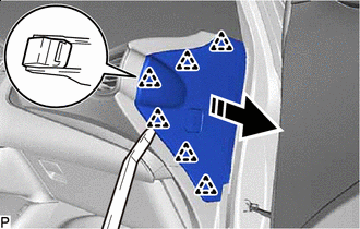
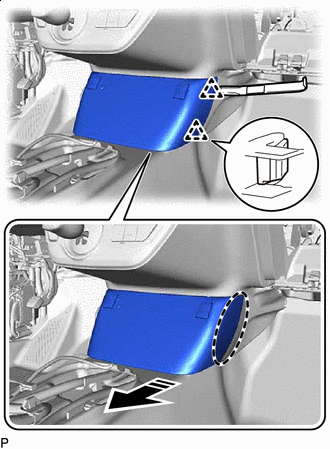
REMOVE INSTRUMENT PANEL FINISH PANEL END LH
-
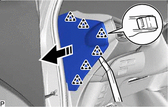

Remove in this Direction Using a moulding remover, disengage the 6 clips as shown in the illustration.
-
Remove in this Direction Disengage the 3 guides to remove the instrument panel finish panel end LH as shown in the illustration.
-
-
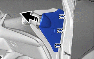
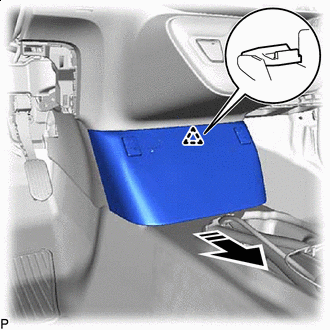
REMOVE INSTRUMENT CLUSTER FINISH PANEL GARNISH ASSEMBLY
-


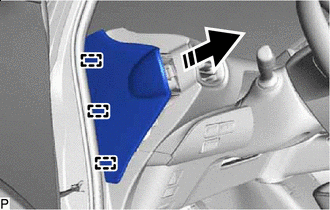
Place Hand Here Remove in this Direction Disengage the 4 clips and claw as shown in the illustration.
-
Disconnect each connector to remove the instrument cluster finish panel garnish assembly.
-
-
REMOVE FRONT DOOR SCUFF PLATE LH
-
REMOVE COWL SIDE TRIM BOARD LH
-
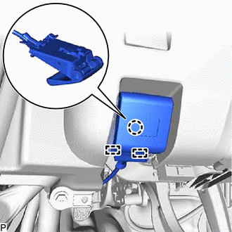
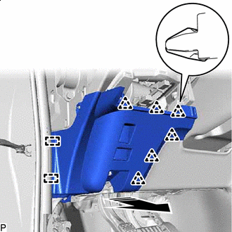
REMOVE NO. 1 INSTRUMENT PANEL UNDER COVER SUB-ASSEMBLY
-
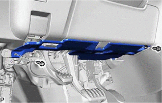
Remove the 2 screws <F>.
-
Remove in this Direction Disengage the claw as shown in the illustration.
-
Remove in this Direction Disengage the guide as shown in the illustration.
-
for LHD:
-
Disconnect the connector to remove the No. 1 instrument panel under cover sub-assembly.
-
-
for RHD:
-
Disconnect the connector.
-

Disengage the 2 claws to disconnect the DLC3 connector.
-
Disengage the clamp to remove the No. 1 instrument panel under cover sub-assembly.
-
-
-
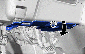
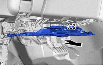
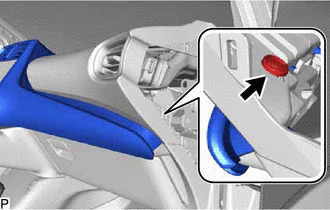
DISCONNECT HOOD LOCK CONTROL LEVER SUB-ASSEMBLY
-
Disengage the claw and 2 guides to disconnect the hood lock control lever sub-assembly.
-
-
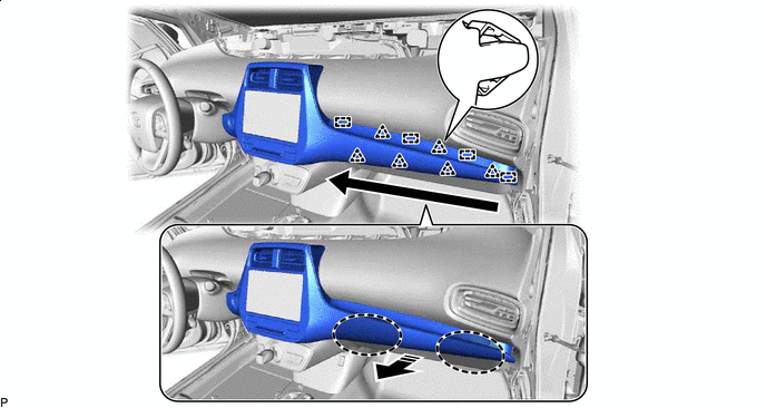
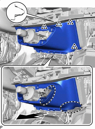
REMOVE LOWER INSTRUMENT PANEL FINISH PANEL ASSEMBLY
-

Remove the screw <C>.
-
Remove in this Direction Disengage the 6 clips and 2 guides as shown in the illustration.
-
Disconnect each connector to remove the lower instrument panel finish panel assembly.
-
-
REMOVE LOWER NO. 1 INSTRUMENT PANEL AIRBAG ASSEMBLY
-
REMOVE COMBINATION METER ASSEMBLY
-
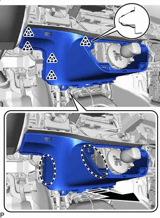
REMOVE INSTRUMENT PANEL FINISH PANEL END RH
-
Remove in this Direction Using a moulding remover, disengage the 6 clips as shown in the illustration.
-
Remove in this Direction Disengage the 3 guides as shown in the illustration.
-
Disconnect the connector to remove the instrument panel finish panel end RH.
-
-
REMOVE CENTER INSTRUMENT CLUSTER FINISH PANEL SUB-ASSEMBLY
-
for LHD:
-
Remove the clip.
-
-
Disengage the 6 clips and 4 guides as shown in the illustration.
Place Hand Here Remove in this Direction 
Order of Removal - - -
Disengage the 12 clips and guide as shown in the illustration.
Place Hand Here Remove in this Direction -
Disconnect each connector.
-
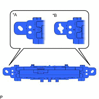
*A for Type A *B for Type B Determine the type of air conditioning control assembly according to the illustration.
-
for Type A:
-
Remove the air conditioning control assembly from center instrument cluster finish panel sub-assembly and then disengage the clamp as shown in the illustration.
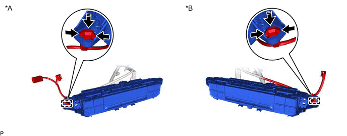
*A for LHD *B for RHD Push Remove in this Direction
-
-
for Type B:
-
Remove in this Direction Disengage the clamp as shown in the illustration.
-
-
Remove the center instrument cluster finish panel sub-assembly.
-
-
REMOVE RADIO AND DISPLAY RECEIVER ASSEMBLY (for Radio and Display Type with 8 Inch Display)
-
REMOVE RADIO RECEIVER ASSEMBLY WITH BRACKET (for Radio and Display Type with 7 Inch Display)
-
REMOVE NAVIGATION RECEIVER ASSEMBLY WITH BRACKET (for Navigation Receiver Type)
-
REMOVE NAVIGATION ECU WITH BRACKET (for Radio and Display Type with 8 Inch Display)
-
REMOVE FRONT DOOR SCUFF PLATE RH
Tech Tips
Use the same procedure as for the LH side.
-
REMOVE COWL SIDE TRIM BOARD RH
Tech Tips
Use the same procedure as for the LH side.
-
REMOVE NO. 2 INSTRUMENT PANEL UNDER COVER SUB-ASSEMBLY
-
Remove in this Direction Disengage the 3 claws as shown in the illustration.
-
Remove in this Direction Disengage the 2 guides as shown in the illustration.
-
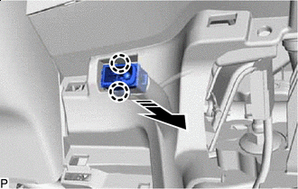
Disconnect the connector to remove the No. 2 instrument panel under cover sub-assembly.
-
-
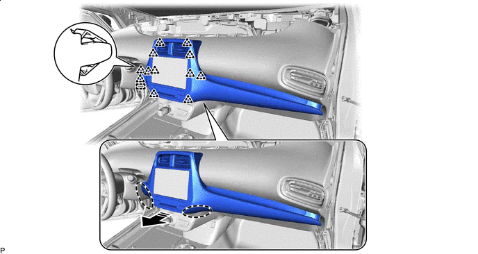
REMOVE GLOVE COMPARTMENT DOOR ASSEMBLY
-
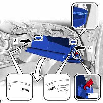
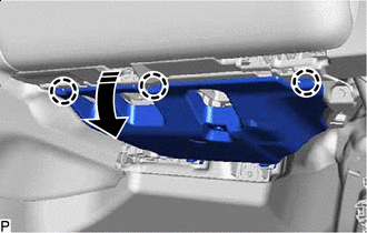
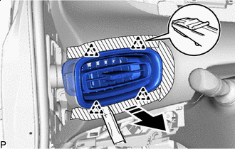
*1 Glove Compartment Door Stopper Sub-assembly Disengage the claw to disconnect the glove compartment door stopper sub-assembly.
-
Slightly bend the stoppers (A) and (B) in the directions indicated by the arrows shown in the illustration and open the glove compartment door assembly until the stoppers are released.
-
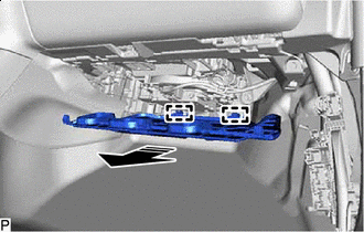
Open the glove compartment door assembly to approximately 64.2° from its closed position. Pull it horizontally as shown in the illustration to disengage the 2 hinges and remove the glove compartment door assembly.
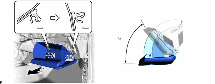
*a 64.2° - - Remove in this Direction - - Note
Pulling the glove compartment door assembly upward when removing it will cause the hinges to deform. Be sure to pull out the glove compartment door assembly horizontally.
-
-
REMOVE GLOVE COMPARTMENT DOOR STOPPER SUB-ASSEMBLY
-

Disengage the claw to remove the glove compartment door stopper sub-assembly.
-
-
REMOVE LOWER CENTER INSTRUMENT CLUSTER FINISH PANEL SUB-ASSEMBLY
-
Insert Moulding Remover Here Remove in this Direction Using a moulding remover, disengage the 2 clips as shown in the illustration.
-

Insert Moulding Remover Here Remove in this Direction Using a moulding remover, disengage the 2 clips as shown in the illustration.
-
Remove in this Direction Disengage the clip as shown in the illustration.
-
Disconnect each connector.
-
Disengage each clamp to remove the lower center instrument cluster finish panel sub-assembly.
-
-
REMOVE SHIFTING HOLE COVER
-

Remove in this Direction Using a moulding remover, disengage the 5 clips as shown in the illustration.
-
Disconnect each connector to remove the shifting hole cover.
-
-
REMOVE NO. 2 LOWER INSTRUMENT PANEL FINISH PANEL
-
Place Hand Here Remove in this Direction Disengage the 4 clips as shown in the illustration.
-
Place Hand Here Remove in this Direction Disengage the 5 clips to remove the No. 2 lower instrument panel finish panel as shown in the illustration.
-
-
REMOVE NO. 1 INSTRUMENT PANEL REGISTER ASSEMBLY
-


Protective Tape Apply protective tape to the areas shown in the illustration.
-
Remove in this Direction Using a moulding remover, disengage the 4 clips to remove the No. 1 instrument panel register assembly as shown in the illustration.
-
-
REMOVE NO. 2 INSTRUMENT PANEL REGISTER ASSEMBLY
-

Protective Tape Apply protective tape to the areas shown in the illustration.
-

Remove in this Direction Using a moulding remover, disengage the 4 clips to remove the No. 2 instrument panel register assembly as shown in the illustration.
-
-
REMOVE GLOVE BOX LIGHT ASSEMBLY
-
DISCONNECT NO. 2 INSTRUMENT PANEL WIRE
-
REMOVE LOWER INSTRUMENT PANEL SUB-ASSEMBLY
-

Disengage the 2 claws and 4 clips to disconnect the lower instrument cover sub-assembly from the upper steering column cover.
-
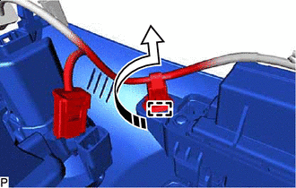
Remove in this Direction Disengage the 2 claws to disconnect the cooler (room temp. sensor) thermistor as shown in the illustration.
-
Disconnect each connector.
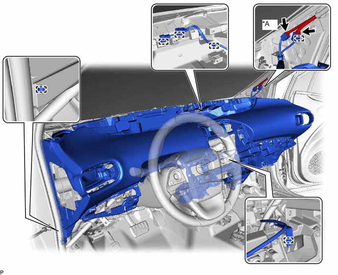
*A w/ Digital Audio Broadcasting Antenna or Television Antenna - - -
Disengage each clamp.
-
Remove the 2 clips.

*a Bolt <A> *b Bolt <B> *c Screw <C> or <G> *d Screw <D> *e Clip - - -
Remove the 2 bolts <A>, 4 bolts <B>, 3 screws <C> or <G>, screw <D> and lower instrument panel sub-assembly.
Note
-
Do not damage the lower instrument panel sub-assembly.
-
Do not allow the wire harnesses to interfere with the surrounding parts.
-
-