UPPER INSTRUMENT PANEL REASSEMBLY
PROCEDURE
-
INSTALL INSTRUMENT PANEL CUSHION
-
Clean the upper instrument panel assembly surface.
-
Remove the double-sided tape from the upper instrument panel assembly.
-
Wipe off any tape adhesive residue.
-
-
Remove the release paper from a new instrument panel cushion.
Tech Tips
After removing the release paper, keep the exposed adhesive free from foreign matter.
-
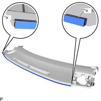
*a Marking Line Align the ends of the instrument panel cushion with the marking lines on the upper instrument panel assembly and install the instrument panel cushion as shown in the illustration.
-
-
INSTALL SPARE SWITCH HOLE COVER (for RHD)
-
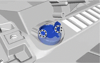
Engage the 2 claws to install the spare switch hole cover.
-
-
INSTALL NO. 2 INSTRUMENT PANEL WIRE
-
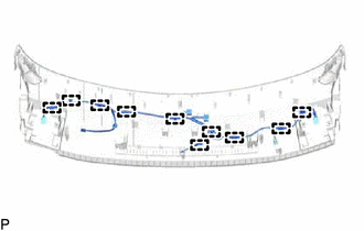
Engage the 10 clamps to install the No. 2 instrument panel wire.
-
-
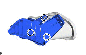
INSTALL SIDE DEFROSTER NOZZLE RH
-
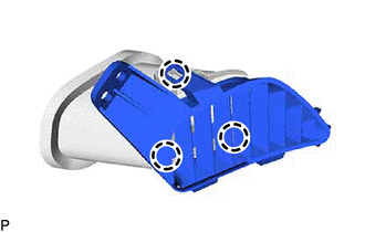
Engage the 3 claws to install the side defroster nozzle RH.
-
-
INSTALL SIDE DEFROSTER NOZZLE ASSEMBLY RH
-
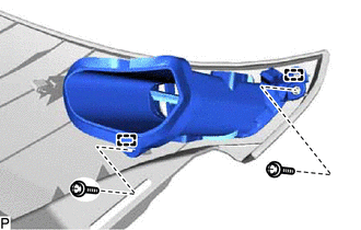
Engage the 2 guides.
-
Install the side defroster nozzle assembly RH with the 2 screws <A>.
-
-
INSTALL SIDE DEFROSTER NOZZLE LH
-
Engage the 3 claws to install the side defroster nozzle LH.
-
-
INSTALL SIDE DEFROSTER NOZZLE ASSEMBLY LH
-
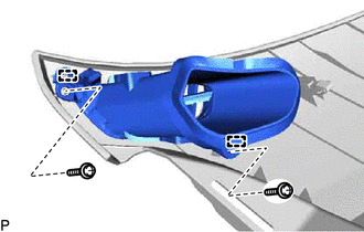
Engage the 2 guides.
-
Install the side defroster nozzle assembly LH with the 2 screws <A>.
-
-
INSTALL ANTENNA CORD SUB-ASSEMBLY (w/ Navigation Antenna)
-
INSTALL NAVIGATION ANTENNA ASSEMBLY WITH BRACKET (w/ Navigation Antenna)
-
INSTALL NO. 1 INSTRUMENT PANEL SPACER
-
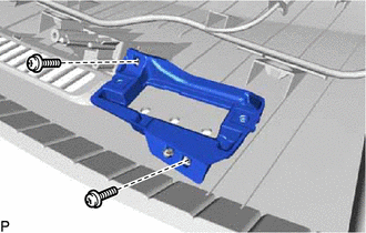
Install the No. 1 instrument panel spacer with the 2 screws <A>.
-
-
INSTALL INDICATOR LIGHT ASSEMBLY
-
INSTALL AUTOMATIC LIGHT CONTROL SENSOR
-
INSTALL DEFROSTER NOZZLE ASSEMBLY
-
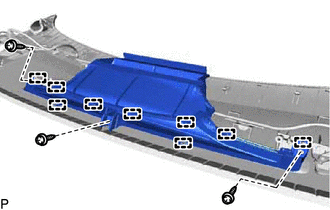
Engage the 9 guides.
-
Install the defroster nozzle assembly with the 3 screws <A>.
-
-
INSTALL NO. 1 INSTRUMENT PANEL PIN
-
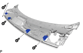
Install the 4 No. 1 instrument panel pins with the 4 screws <A>.
-
-
INSTALL METER MIRROR SUB-ASSEMBLY (w/ Headup Display)