UPPER INSTRUMENT PANEL DISASSEMBLY
PROCEDURE
-
REMOVE METER MIRROR SUB-ASSEMBLY (w/ Headup Display)
-
REMOVE NO. 1 INSTRUMENT PANEL PIN
-
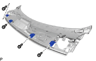
Remove the 4 screws <A> and 4 No. 1 instrument panel pins.
-
-
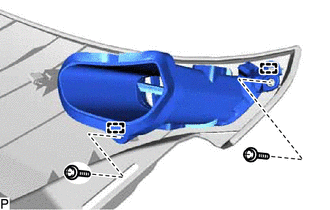
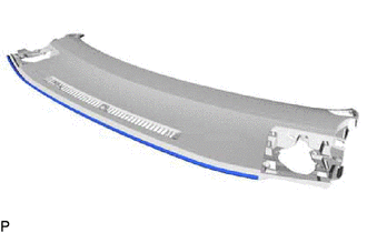
REMOVE DEFROSTER NOZZLE ASSEMBLY
-
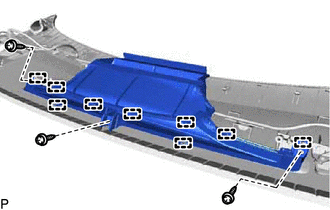
Remove the 3 screws <A>.
-
Disengage the 9 guides to remove the defroster nozzle assembly.
-
-
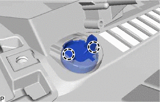
REMOVE AUTOMATIC LIGHT CONTROL SENSOR
-
REMOVE INDICATOR LIGHT ASSEMBLY
-
REMOVE NO. 1 INSTRUMENT PANEL SPACER
-
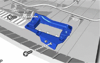
Remove the 2 screws <A> and No. 1 instrument panel spacer.
-
-
REMOVE NAVIGATION ANTENNA ASSEMBLY WITH BRACKET (w/ Navigation Antenna)
-
REMOVE ANTENNA CORD SUB-ASSEMBLY (w/ Navigation Antenna)
-
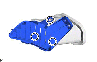
REMOVE SIDE DEFROSTER NOZZLE ASSEMBLY LH
-
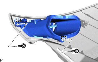
Remove the 2 screws <A>.
-
Disengage the 2 guides to remove the side defroster nozzle assembly LH.
-
-
REMOVE SIDE DEFROSTER NOZZLE LH
-
Disengage the 3 claws to remove the side defroster nozzle LH.
-
-
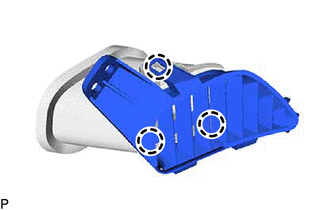
REMOVE SIDE DEFROSTER NOZZLE ASSEMBLY RH
-
Remove the 2 screws <A>.
-
Disengage the 2 guides to remove the side defroster nozzle assembly RH.
-
-
REMOVE SIDE DEFROSTER NOZZLE RH
-
Disengage the 3 claws to remove the side defroster nozzle RH.
-
-
REMOVE NO. 2 INSTRUMENT PANEL WIRE
-
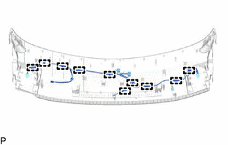
Disengage the 10 clamps to remove the No. 2 instrument panel wire.
-
-
REMOVE SPARE SWITCH HOLE COVER (for RHD)
-
Disengage the 2 claws to remove the spare switch hole cover.
-
-
REMOVE INSTRUMENT PANEL CUSHION
-
Remove the instrument panel cushion.
-