ACCUMULATOR REMOVAL
CAUTION / NOTICE / HINT
The necessary procedures (adjustment, calibration, initialization, or registration) that must be performed after parts are removed and installed, or replaced during accumulator removal/installation are shown below.
| Replaced Part or Performed Procedure | Necessary Procedure | Effect/Inoperative Function when Necessary Procedure not Performed | Link |
|---|---|---|---|
| Front bumper assembly |
|
|
|
| Change grille shutter control modes and/or perform initialization (w/ Exhaust Heat Recirculation System) | Grille Shutter system |
Note
-
When replacing the accumulator and accessory assembly or air conditioning receiver tank with a new one, make sure to weigh the removed accumulator and accessory assembly.
-
As a pipe may deform or its joint may be damaged if force is applied to the pipe, do not carry the accumulator and accessory assembly by a pipe or apply excessive force to a pipe while performing work.
PROCEDURE
-
RECOVER REFRIGERANT FROM REFRIGERATION SYSTEM
for HFC-134a (R134a):
for HFO-1234yf (R1234yf):
-
REMOVE HEADLIGHT ASSEMBLY RH
-
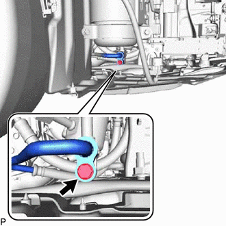
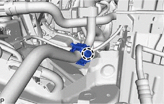
DISCONNECT NO. 2 COOLER REFRIGERANT DISCHARGE HOSE
-
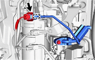
Disconnect the connector.
-
Disengage the clamp.
-
Remove the bolt and disconnect the No. 2 cooler refrigerant discharge hose from the acuumulator and accessory assembly.
-
Remove the O-ring from the No. 2 cooler refrigerant discharge hose.
Note
Seal the openings of the disconnected parts using vinyl tape to prevent entry of moisture and foreign matter.
-
-
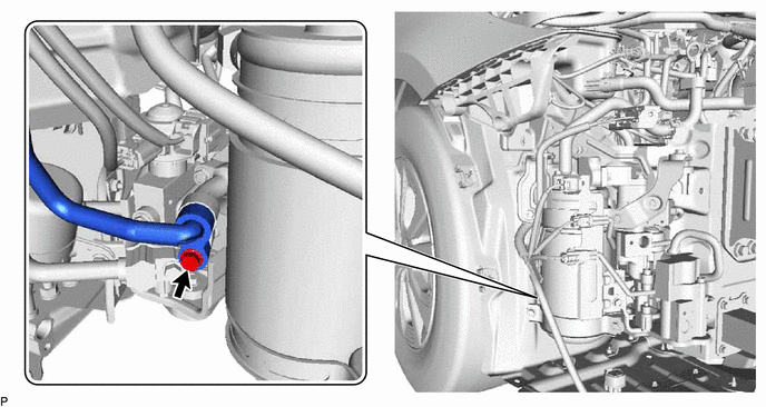
DISCONNECT NO. 1 COOLER REFRIGERANT DISCHARGE HOSE
-
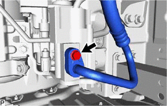
Remove the bolt and disconnect the No. 1 cooler refrigerant discharge hose from the acuumulator and accessory assembly.
-
Remove the O-ring from the No. 1 cooler refrigerant discharge hose.
Note
Seal the openings of the disconnected parts using vinyl tape to prevent entry of moisture and foreign matter.
-
-
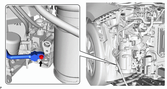
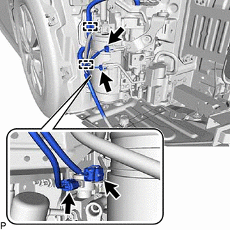
DISCONNECT SUCTION TUBE SUB-ASSEMBLY
-
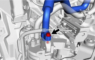
Remove the bolt and disconnect the suction tube sub-assembly from the acuumulator and accessory assembly.
-
Remove the O-ring from the suction tube sub-assembly.
Note
Seal the openings of the disconnected parts using vinyl tape to prevent entry of moisture and foreign matter.
-
-
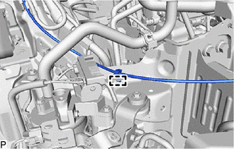
DISCONNECT SUCTION HOSE SUB-ASSEMBLY
-
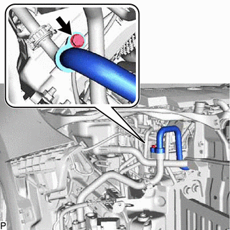
Remove the bolt and disconnect the suction hose sub-assembly from the acuumulator and accessory assembly.
-
Remove the O-ring from the suction hose sub-assembly.
Note
Seal the openings of the disconnected parts using vinyl tape to prevent entry of moisture and foreign matter.
-
-
DISCONNECT NO. 1 DISCHARGE HOSE SUB-ASSEMBLY
-
Remove the bolt and disconnect the No. 1 discharge hose sub-assembly from the acuumulator and accessory assembly.
-
Remove the O-ring from the No. 1 discharge hose sub-assembly.
Note
Seal the openings of the disconnected parts using vinyl tape to prevent entry of moisture and foreign matter.
-
-
DISCONNECT DISCHARGE PIPE SUB-ASSEMBLY
-
Remove the bolt and disconnect the discharge pipe sub-assembly from the acuumulator and accessory assembly.
-
Remove the O-ring from the discharge pipe sub-assembly.
Note
Seal the openings of the disconnected parts using vinyl tape to prevent entry of moisture and foreign matter.
-
-
DISCONNECT DISCHARGE TUBE SUB-ASSEMBLY
-
Remove the bolt and disconnect the discharge tube sub-assembly from the acuumulator and accessory assembly.
-
Remove the O-ring from the discharge tube sub-assembly.
Note
Seal the openings of the disconnected parts using vinyl tape to prevent entry of moisture and foreign matter.
-
-
REMOVE ACCUMULATOR AND ACCESSORY ASSEMBLY
-
for RHD:
-
Disengage the clamp to disconnect the hood lock control cable assembly from the acuumulator and accessory assembly.
-
-
Disengage the claw.
-
Disengage the 2 clamps.
-
Disconnect each connector.
-
Remove the 2 bolts and 2 nuts.
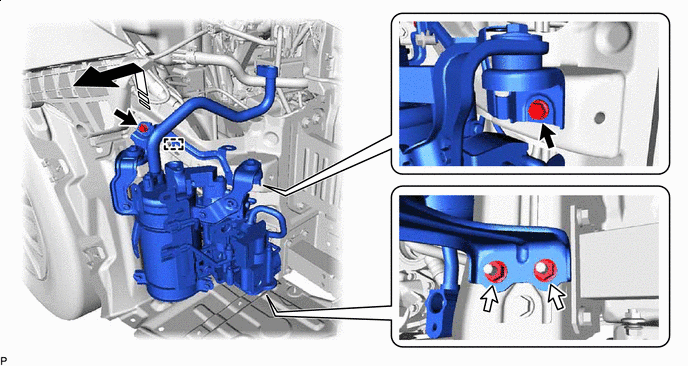

Remove in this Direction 
Bolt 
Nut - - -
Disengage the guide to remove the acuumulator and accessory assembly as shown in the illustration.
-