ACCUMULATOR INSTALLATION
PROCEDURE
-
ADJUST COMPRESSOR OIL
-
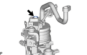
When using a new accumulator and accessory assembly or air conditioning receiver tank:
-
Add compressor oil into the opening shown in the illustration until the weight of the accumulator and accessory assembly is the same as measured during removal.
Note
-
As new accumulator and accessory assemblies and receiver air conditioning tanks do not contain compressor oil, make sure to add the necessary amount of compressor oil to the accumulator and accessory assembly.
-
Be sure to use ND-OIL 11 or equivalent compressor oil.
-
-
-
-
INSTALL ACCUMULATOR AND ACCESSORY ASSEMBLY
-
Engage the guide to install the acuumulator and accessory assembly as shown in the illustration.
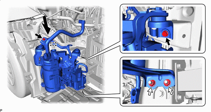

Install in this Direction 
Bolt 
Nut - - -
Install the 2 bolts and 2 nuts.
- Torque:
- 9.8 N*m { 100 kgf*cm, 87 in.*lbf }
-
Connect each connector.
-
Engage the 2 clamps.
-
Engage the claw.
-
for RHD:
-
Engage the clamp to connect the hood lock control cable assembly to the acuumulator and accessory assembly.
-
-
-
CONNECT DISCHARGE TUBE SUB-ASSEMBLY
-
Remove the vinyl tape from the discharge tube sub-assembly and the connecting part of the acuumulator and accessory assembly.
-
Sufficiently apply compressor oil to a new O-ring and the fitting surface of the discharge tube sub-assembly.
Compressor Oil ND-OIL 11 or equivalent -
Install the O-ring to the discharge tube sub-assembly.
Note
Keep the O-ring and O-ring fitting surface free of foreign matter.
-
Connect the discharge tube sub-assembly to the acuumulator and accessory assembly with the bolt.
- Torque:
- 9.8 N*m { 100 kgf*cm, 87 in.*lbf }
-
-
CONNECT DISCHARGE PIPE SUB-ASSEMBLY
-
Remove the vinyl tape from the discharge pipe sub-assembly and the connecting part of the acuumulator and accessory assembly.
-
Sufficiently apply compressor oil to a new O-ring and the fitting surface of the discharge pipe sub-assembly.
Compressor Oil ND-OIL 11 or equivalent -
Install the O-ring to the discharge pipe sub-assembly.
Note
Keep the O-ring and O-ring fitting surface free of foreign matter.
-
Connect the discharge pipe sub-assembly to the acuumulator and accessory assembly with the bolt.
- Torque:
- 9.8 N*m { 100 kgf*cm, 87 in.*lbf }
-
-
CONNECT NO. 1 DISCHARGE HOSE SUB-ASSEMBLY
-
Remove the vinyl tape from the No. 1 discharge hose sub-assembly and the connecting part of the acuumulator and accessory assembly.
-
Sufficiently apply compressor oil to a new O-ring and the fitting surface of the No. 1 discharge hose sub-assembly.
Compressor Oil ND-OIL 11 or equivalent -
Install the O-ring to the No. 1 discharge hose sub-assembly.
Note
Keep the O-ring and O-ring fitting surface free of foreign matter.
-
Connect the No. 1 discharge hose sub-assembly to the acuumulator and accessory assembly with the bolt.
- Torque:
- 9.8 N*m { 100 kgf*cm, 87 in.*lbf }
-
-
CONNECT SUCTION HOSE SUB-ASSEMBLY
-
Remove the vinyl tape from the suction hose sub-assembly and the connecting part of the acuumulator and accessory assembly.
-
Sufficiently apply compressor oil to a new O-ring and the fitting surface of the suction hose sub-assembly.
Compressor Oil ND-OIL 11 or equivalent -
Install the O-ring to the suction hose sub-assembly.
Note
Keep the O-ring and O-ring fitting surface free of foreign matter.
-
Connect the suction hose sub-assembly to the acuumulator and accessory assembly with the bolt.
- Torque:
- 9.8 N*m { 100 kgf*cm, 87 in.*lbf }
-
-
CONNECT SUCTION TUBE SUB-ASSEMBLY
-
Remove the vinyl tape from the suction tube sub-assembly and the connecting part of the acuumulator and accessory assembly.
-
Sufficiently apply compressor oil to a new O-ring and the fitting surface of the suction tube sub-assembly.
Compressor Oil ND-OIL 11 or equivalent -
Install the O-ring to the suction tube sub-assembly.
Note
Keep the O-ring and O-ring fitting surface free of foreign matter.
-
Connect the suction tube sub-assembly to the acuumulator and accessory assembly with the bolt.
- Torque:
- 9.8 N*m { 100 kgf*cm, 87 in.*lbf }
-
-
CONNECT NO. 1 COOLER REFRIGERANT DISCHARGE HOSE
-
Remove the vinyl tape from the No. 1 cooler refrigerant discharge hose and the connecting part of the acuumulator and accessory assembly.
-
Sufficiently apply compressor oil to a new O-ring and the fitting surface of the No. 1 cooler refrigerant discharge hose.
Compressor Oil ND-OIL 11 or equivalent -
Install the O-ring to the No. 1 cooler refrigerant discharge hose.
Note
Keep the O-ring and O-ring fitting surface free of foreign matter.
-
Connect the No. 1 cooler refrigerant discharge hose to the acuumulator and accessory assembly with the bolt.
- Torque:
- 9.8 N*m { 100 kgf*cm, 87 in.*lbf }
-
-
CONNECT NO. 2 COOLER REFRIGERANT DISCHARGE HOSE
-
Remove the vinyl tape from the No. 2 cooler refrigerant discharge hose and the connecting part of the acuumulator and accessory assembly.
-
Sufficiently apply compressor oil to a new O-ring and the fitting surface of the No. 2 cooler refrigerant discharge hose.
Compressor Oil ND-OIL 11 or equivalent -
Install the O-ring to the No. 2 cooler refrigerant discharge hose.
Note
Keep the O-ring and O-ring fitting surface free of foreign matter.
-
Connect the No. 2 cooler refrigerant discharge hose to the acuumulator and accessory assembly with the bolt.
- Torque:
- 9.8 N*m { 100 kgf*cm, 87 in.*lbf }
-
Engage the clamp.
-
Connect the connector.
-
-
INSTALL HEADLIGHT ASSEMBLY RH
-
CHARGE AIR CONDITIONING SYSTEM WITH REFRIGERANT
for HFC-134a (R134a):
for HFO-1234yf (R1234yf):
-
WARM UP COMPRESSOR
for HFC-134a (R134a):
for HFO-1234yf (R1234yf):
-
INSPECT FOR REFRIGERANT LEAK
for HFC-134a (R134a):
for HFO-1234yf (R1234yf):