CONDENSER INSTALLATION
PROCEDURE
-
INSTALL COOLER CONDENSER ASSEMBLY
-
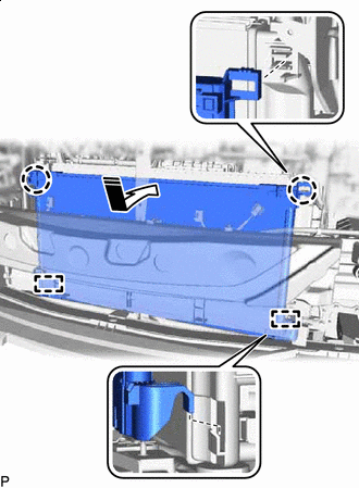

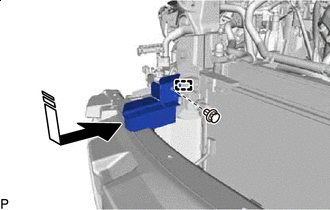
Install in this Direction Engage the 2 guides and 2 claws to install the cooler condenser assembly as shown in the illustration.
Note
Do not damage the cooler condenser assembly or radiator assembly when installing the cooler condenser assembly.
Tech Tips
If a new cooler condenser assembly is installed, add compressor oil to the cooler condenser assembly as follows.
Capacity Add 40 cc (1.35 fl. oz) Compressor Oil ND-OIL 11 or equivalent
-
-
INSTALL NO. 1 RADIATOR AIR GUIDE LH
-
Install in this Direction Engage the guide and claw to install a new No. 1 radiator air guide LH as shown in the illustration.
-
-
INSTALL NO. 3 RADIATOR TO SUPPORT SEAL
-
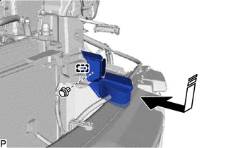
Install in this Direction Engage the guide to install the No. 3 radiator to support seal as shown in the illustration.
-
Install the clip.
-
-
INSTALL NO. 1 RADIATOR AIR GUIDE RH
-
Install in this Direction Engage the guide and claw to install a new No. 1 radiator air guide RH as shown in the illustration.
-
-
INSTALL NO. 2 RADIATOR TO SUPPORT SEAL
-
Install in this Direction Engage the guide to install the No. 2 radiator to support seal as shown in the illustration.
-
Install the clip.
-
-
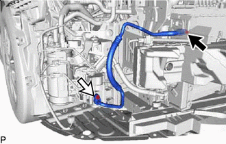
INSTALL NO. 2 COOLER REFRIGERANT DISCHARGE HOSE
-
Remove the vinyl tape from the No. 2 cooler refrigerant discharge hose.
-
Sufficiently apply compressor oil to 2 new O-rings and the fitting surfaces of the No. 2 cooler refrigerant discharge hose.
Compressor Oil ND-OIL 11 or equivalent -
Install the 2 O-rings to the No. 2 cooler refrigerant discharge hose.
Note
Keep the O-rings and O-ring fitting surfaces free of foreign matter.
-

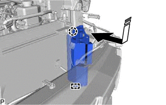
Bolt (A) 
Connector 
Bolt (B) Connect the No. 2 cooler refrigerant discharge hose with the bolt (A).
- Torque:
- 9.8 N*m { 100 kgf*cm, 87 in.*lbf }
-
Engage the clamp.
-
Connect the connector.
-
Install the No. 2 cooler refrigerant discharge hose with the bolt (B).
- Torque:
- 5.4 N*m { 55 kgf*cm, 48 in.*lbf }
-
-
INSTALL NO. 1 COOLER REFRIGERANT DISCHARGE HOSE
-
Remove the vinyl tape from the No. 1 cooler refrigerant discharge hose.
-
Sufficiently apply compressor oil to 2 new O-rings and the fitting surfaces of the No. 1 cooler refrigerant discharge hose.
Compressor Oil ND-OIL 11 or equivalent -
Install the 2 O-rings to the No. 1 cooler refrigerant discharge hose.
Note
Keep the O-rings and O-ring fitting surfaces free of foreign matter.
-
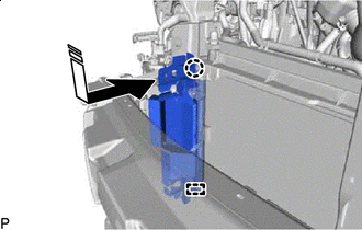
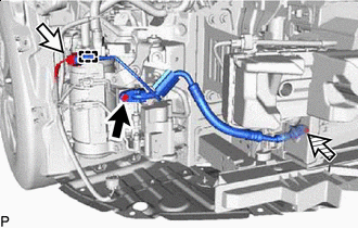
Bolt (A) Bolt (B) Connect the No. 1 cooler refrigerant discharge hose with the bolt (A).
- Torque:
- 5.4 N*m { 55 kgf*cm, 48 in.*lbf }
-
Install the No. 1 cooler refrigerant discharge hose with the bolt (B).
- Torque:
- 9.8 N*m { 100 kgf*cm, 87 in.*lbf }
-
-
INSTALL NO. 2 RADIATOR AIR GUIDE
-
INSTALL UPPER RADIATOR SUPPORT SUB-ASSEMBLY
-
INSTALL INLET NO. 2 AIR CLEANER
-
INSTALL HOOD LOCK ASSEMBLY
-
INSTALL HEADLIGHT ASSEMBLY LH
-
INSTALL HEADLIGHT ASSEMBLY RH
Tech Tips
Use the same procedure as for the LH side.
-
CHARGE AIR CONDITIONING SYSTEM WITH REFRIGERANT
for HFC-134a (R134a):
for HFO-1234yf (R1234yf):
-
WARM UP COMPRESSOR
for HFC-134a (R134a):
for HFO-1234yf (R1234yf):
-
INSPECT FOR REFRIGERANT LEAK
for HFC-134a (R134a):
for HFO-1234yf (R1234yf):
-
ADJUST HOOD SUB-ASSEMBLY