CONDENSER REMOVAL
CAUTION / NOTICE / HINT
The necessary procedures (adjustment, calibration, initialization, or registration) that must be performed after parts are removed and installed, or replaced during condenser removal/installation are shown below.
| Replaced Part or Performed Procedure | Necessary Procedure | Effect/Inoperative Function when Necessary Procedure not Performed | Link |
|---|---|---|---|
| Front bumper assembly |
|
|
|
| Change grille shutter control modes and/or perform initialization (w/ Exhaust Heat Recirculation System) | Grille Shutter system |
PROCEDURE
-
RECOVER REFRIGERANT FROM REFRIGERATION SYSTEM
for HFC-134a (R134a):
for HFO-1234yf (R1234yf):
-
REMOVE HEADLIGHT ASSEMBLY LH
-
REMOVE HEADLIGHT ASSEMBLY RH
Tech Tips
Use the same procedure as for the LH side.
-
REMOVE HOOD LOCK ASSEMBLY
-
REMOVE INLET NO. 2 AIR CLEANER
-
REMOVE UPPER RADIATOR SUPPORT SUB-ASSEMBLY
-
REMOVE NO. 2 RADIATOR AIR GUIDE
-
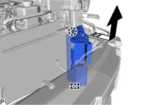
REMOVE NO. 1 COOLER REFRIGERANT DISCHARGE HOSE
-
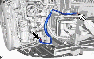

Bolt (A) 
Bolt (B) Remove the bolt (A) and disconnect the No. 1 cooler refrigerant discharge hose.
-
Remove the bolt (B) and No. 1 cooler refrigerant discharge hose.
-
Remove the 2 O-rings from the No. 1 cooler refrigerant discharge hose.
Note
Seal the openings of the disconnected parts using vinyl tape to prevent entry of moisture and foreign matter.
-
-
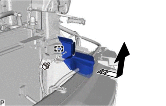
REMOVE NO. 2 COOLER REFRIGERANT DISCHARGE HOSE
-
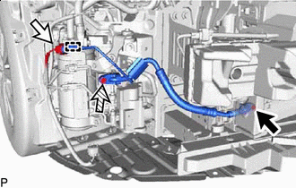
Bolt (A) Connector 
Bolt (B) Remove the bolt (A) and disconnect the No. 2 cooler refrigerant discharge hose.
-
Disconnect the connector.
-
Disengage the clamp.
-
Remove the bolt (B) and No. 2 cooler refrigerant discharge hose.
-
Remove the 2 O-rings from the No. 2 cooler refrigerant discharge hose.
Note
Seal the openings of the disconnected parts using vinyl tape to prevent entry of moisture and foreign matter.
-
-
REMOVE NO. 2 RADIATOR TO SUPPORT SEAL
-
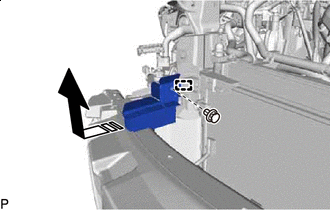

Remove in this Direction Remove the clip.
-
Disengage the guide and remove the No. 2 radiator to support seal as shown in the illustration.
-
-
REMOVE NO. 1 RADIATOR AIR GUIDE RH
-
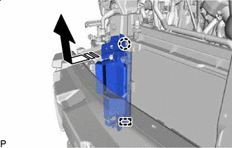
Remove in this Direction Disengage the claw and guide, and remove the No. 1 radiator air guide RH as shown in the illustration.
-
-
REMOVE NO. 3 RADIATOR TO SUPPORT SEAL
-
Remove in this Direction Remove the clip.
-
Disengage the guide and remove the No. 3 radiator to support seal as shown in the illustration.
-
-
REMOVE NO. 1 RADIATOR AIR GUIDE LH
-
Remove in this Direction Disengage the claw and guide, and remove the No. 1 radiator air guide LH as shown in the illustration.
-
-
REMOVE COOLER CONDENSER ASSEMBLY
-
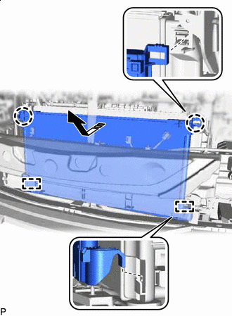
Remove in this Direction Disengage the 2 claws and 2 guides, and remove the cooler condenser assembly as shown in the illustration.
Note
Do not damage the cooler condenser assembly or radiator assembly when removing the cooler condenser assembly.
-