COMPRESSOR REMOVAL
CAUTION / NOTICE / HINT
The necessary procedures (adjustment, calibration, initialization, or registration) that must be performed after parts are removed and installed, or replaced during compressor removal/installation are shown below.
| Replaced Part or Performed Procedure | Necessary Procedures | Effect/Inoperative Function when Necessary Procedure not Performed | Link |
|---|---|---|---|
| Disconnect cable from negative auxiliary battery terminal | Memorize steering angle neutral point | Lane departure alert system (w/ Steering Control) | |
| Intelligent clearance sonar system*1 | |||
| Simple intelligent parking assist system*1 | |||
| Pre-crash safety system | |||
| Adaptive high beam system | |||
| Parking assist monitor system | |||
| Initialize back door lock | Power door lock control system |
Click here Click here
CAUTION:
-
Orange wire harnesses and connectors indicate high-voltage circuits. To prevent electric shock, always follow the procedure described in the repair manual.
-

To prevent electric shock, wear insulated gloves when working on wire harnesses and components of the high voltage system.
PROCEDURE
-
RECOVER REFRIGERANT FROM REFRIGERATION SYSTEM
for HFC-134a (R134a):
for HFO-1234yf (R1234yf):
-
REMOVE SERVICE PLUG GRIP
-
CHECK TERMINAL VOLTAGE
-
Remove the windshield wiper motor and link assembly.
-
for LHD:
-
Remove the No. 1 heater air duct splash shield seal.
-
-
for RHD:
-
Remove the No. 2 heater air duct splash shield seal.
-
-
Remove the water guard plate.
-
Remove the cowl body mounting reinforcement LH.
-
Remove the outer cowl top panel sub-assembly.
-
w/o Canister Pump Module:
-
Remove the No. 1 engine cover sub-assembly.
-
-
w/o Canister Pump Module:
-
Disconnect the engine wire.
-
-
w/ Canister Pump Module:
-
Disconnect the engine wire.
-
-
Remove the connector cover assembly.
-
Check the terminal voltage.
-
Install the connector cover assembly.
-
w/ Canister Pump Module:
-
Connect the engine wire.
-
-
w/o Canister Pump Module:
-
Connect the engine wire.
-
-
w/o Canister Pump Module:
-
Install the No. 1 engine cover sub-assembly.
-
-
Install the outer cowl top panel sub-assembly.
-
Install the cowl body mounting reinforcement LH.
-
Install the water guard plate.
-
for LHD:
-
Install the No. 1 heater air duct splash shield seal.
-
-
for RHD:
-
Install the No. 2 heater air duct splash shield seal.
-
-
Install the windshield wiper motor and link assembly.
-
-
REMOVE RADIATOR SUPPORT OPENING COVER
-
REMOVE INLET NO. 2 AIR CLEANER
-
REMOVE AIR CLEANER CAP SUB-ASSEMBLY
-
REMOVE AIR CLEANER FILTER ELEMENT SUB-ASSEMBLY
-
REMOVE AIR CLEANER CASE SUB-ASSEMBLY
-
REMOVE AIR CLEANER BRACKET
-
REMOVE SUCTION HOSE SUB-ASSEMBLY
-
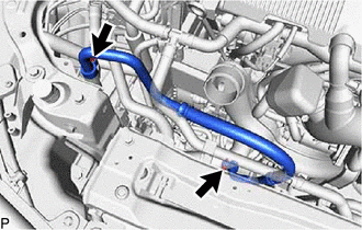
Remove the 2 bolts and suction hose sub-assembly.
-
Remove the 2 O-rings from the suction hose sub-assembly.
Note
Seal the openings of the disconnected parts using vinyl tape to prevent moisture and foreign matter from entering them.
-
-
REMOVE INLET NO. 1 AIR CLEANER
-
Remove the 2 bolts and inlet No. 1 air cleaner.
-
-
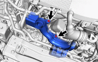
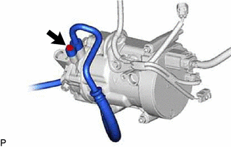
DISCONNECT DISCHARGE HOSE SUB-ASSEMBLY
-
Remove the bolt and disconnect the discharge hose sub-assembly from the compressor with motor assembly.
-
Remove the O-ring from the discharge hose sub-assembly.
Note
Seal the openings of the disconnected parts using vinyl tape to prevent moisture and foreign matter from entering them.
-
-
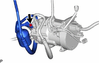
DISCONNECT NO. 1 DISCHARGE HOSE SUB-ASSEMBLY
-
Remove the bolt and disconnect the No. 1 discharge hose sub-assembly from the compressor with motor assembly.
-
Remove the O-ring from the No. 1 discharge hose sub-assembly.
Note
Seal the openings of the disconnected parts using vinyl tape to prevent moisture and foreign matter from entering them.
-
-
REMOVE COMPRESSOR WITH MOTOR ASSEMBLY
-
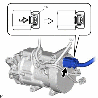
*a Green-colored Lock 
Slide Using a screwdriver, slide the green-colored lock of the connector as shown in the illustration to release it and disconnect the connector.
CAUTION:
Make sure to wear insulated gloves.
Note
Insulate the disconnected terminals and connector with insulating tape.
-
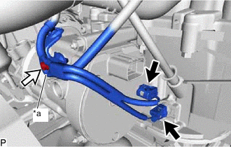
*a Bracket Disconnect the 2 connectors.
-
Remove the bolt and disconnect the bracket.
-
for Type A:
-
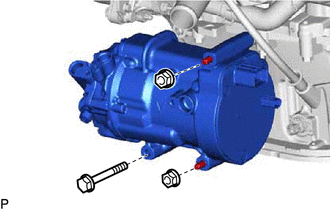
Remove the bolt and 2 nuts.
-
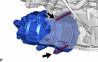
Using an E8 "TORX" socket wrench, remove the 2 stud bolts and compressor with motor assembly.
-
-
for Type B:
-
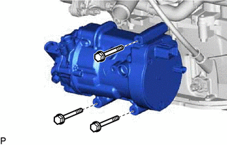
Remove the 3 bolts and compressor with motor assembly.
-
-