AIR CONDITIONING UNIT DISASSEMBLY
PROCEDURE
-
PRECAUTION
Note
Make sure to perform initialization after replacing the air conditioning radiator damper servo sub-assembly. If initialization is not performed, the air conditioner unit assembly will not perform properly as the air conditioning amplifier assembly will not be able to recognize the position of the air conditioning radiator damper sub-assembly.
-
REMOVE NO. 2 AIR DUCT (for LHD)
-
Remove the screw.
-
Disengage the 3 claws to remove the No. 2 air duct.
-
-
REMOVE NO. 1 AIR DUCT (for RHD)
-
Remove the screw.
-
Disengage the 3 claws to remove the No. 1 air duct.
-
-
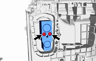
REMOVE ASPIRATOR
-
Disengage the 2 claws to remove the aspirator.
-
-
REMOVE BLOWER ASSEMBLY
-
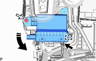
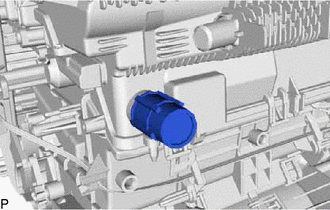
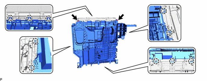
REMOVE AIR CONDITIONING AMPLIFIER ASSEMBLY
-
for LHD:
-
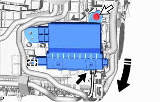

Remove in this Direction Disconnect the connector.
-
Remove the screw.
-
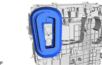
Disengage the guide to remove the air conditioning amplifier assembly as shown in the illustration.
-
-
for RHD:
-
Remove in this Direction Disconnect the connector.
-
Remove the screw.
-
Disengage the guide to remove the air conditioning amplifier assembly as shown in the illustration.
-
-
-
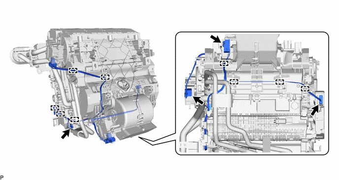
REMOVE AIR CONDITIONING HARNESS ASSEMBLY
-
for LHD:
-
Disconnect each connector.
-
Disengage each clamp to remove the air conditioning harness assembly.
-
-
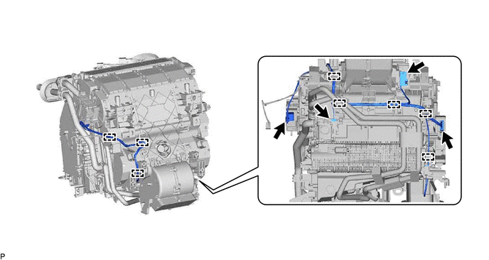
for RHD:
-
Disconnect each connector.
-
Disengage each clamp to remove the air conditioning harness assembly.
-
-
-
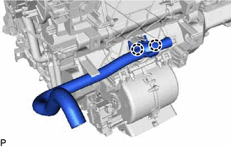
REMOVE DRAIN COOLER HOSE
-
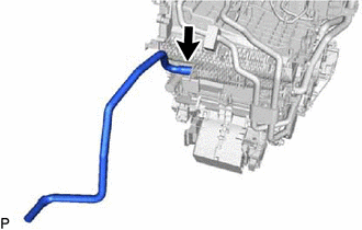
Remove the drain cooler hose.
-
-
REMOVE NO. 1 AIR CONDITIONING RADIATOR DAMPER SERVO SUB-ASSEMBLY
-
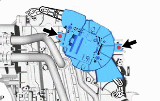
Remove the 2 screws and No. 1 air conditioning radiator damper servo sub-assembly.
-
-
REMOVE NO. 2 AIR CONDITIONING RADIATOR DAMPER SERVO SUB-ASSEMBLY
-
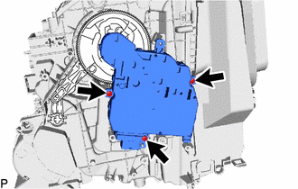
Remove the 3 screws and No. 2 air conditioning radiator damper servo sub-assembly.
-
-
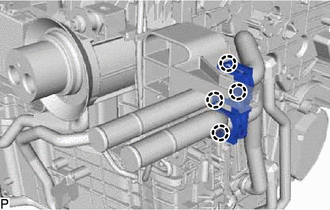
REMOVE NO. 3 AIR CONDITIONING RADIATOR DAMPER SERVO SUB-ASSEMBLY
-
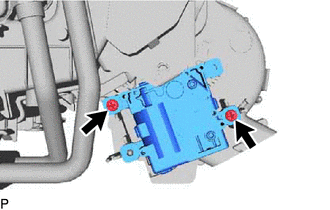
Remove the 2 screws and No. 3 air conditioning radiator damper servo sub-assembly.
-
-
REMOVE HEATER GROMMET
-
Remove the heater grommet.
-
-
REMOVE HEATER CLAMP
-
Disengage the 4 claws to remove the heater clamp.
-
-
REMOVE HEATER RADIATOR UNIT SUB-ASSEMBLY
-
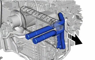
Remove in this Direction Remove the heater radiator unit sub-assembly as shown in the illustration.
Note
Prepare a drain pan or cloth in case the coolant leaks.
-
-
REMOVE GROMMET
-
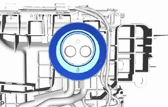
Remove the grommet.
-
-
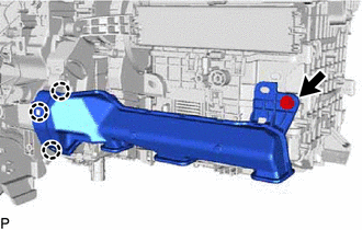
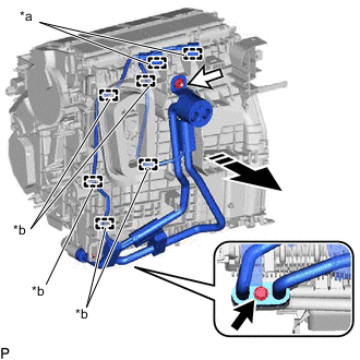
REMOVE NO. 1 DISCHARGE TUBE
-
for LHD:
-
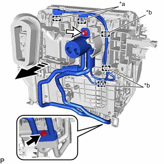
*a Clamp *b Guide 
Bolt 
Nut Remove in this Direction Disengage each clamp and each guide.
-
Remove the bolt, nut and No. 1 discharge tube with thermistor as shown in the illustration.
-
Remove the 2 O-rings from the No. 1 discharge tube.
Note
Seal the openings of the disconnected parts using vinyl tape to prevent entry of moisture and foreign matter.
-
-
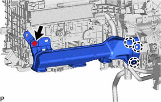
for RHD:
-
*a Clamp *b Guide Bolt Nut Remove in this Direction Disengage each clamp and each guide.
-
Remove the bolt, nut and No. 1 discharge tube with thermistor as shown in the illustration.
-
Remove the 2 O-rings from the No. 1 discharge tube.
Note
Seal the openings of the disconnected parts using vinyl tape to prevent entry of moisture and foreign matter.
-
-
-
REMOVE COOLER PACKING
-
REMOVE INTERNAL CONDENSER TEMPERATURE SENSOR
-
REMOVE COOLER PACKING
-
REMOVE DISCHARGE TEMPERATURE SENSOR
-
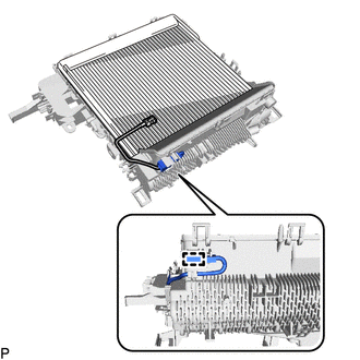
REMOVE DRAIN HOSE
-
Remove the drain hose.
-
-
REMOVE COOLER PIPE GROMMET
-
Remove the cooler pipe grommet.
-
-
REMOVE NO. 1 COOLER EVAPORATOR SUB-ASSEMBLY
-
Using a 4 mm hexagon socket wrench, remove the 2 hexagon bolts and connector tube.
-
Remove the 2 O-rings from the No. 1 cooler evaporator sub-assembly.
-
Remove the 2 screws.
-
Disengage the 10 claws to remove the upper heater case with No. 1 cooler evaporator sub-assembly from the lower heater case.
-
Disengage the clamp.
-
Remove the No. 1 cooler evaporator sub-assembly with evaporator temperature sensor from the upper heater case.
-
-
REMOVE EVAPORATOR TEMPERATURE SENSOR
-
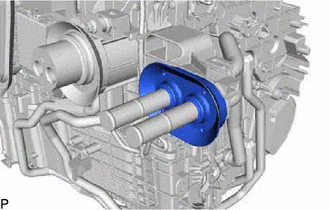
REMOVE NO. 2 CONDENSER ASSEMBLY
-
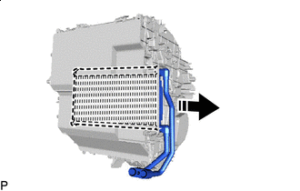
Remove in this Direction Remove the No. 2 condenser assembly as shown in the illustration.
-