AIR CONDITIONING SYSTEM Compressor Operates but Heating Effectiveness is Poor (A/C Switch On)
PROCEDURE
-
PERFORM MIDDLE DIFFERENTIAL PRESSURE VALVE STATE CHECK
-
Perform the middle differential pressure valve state check.
OK Middle differential pressure valve state check is successful. Result Proceed to OK NG
NG 
REPLACE NO. 1 AIR CONDITIONING ACCESSORY ASSEMBLY Click here
OK 
-
-
PERFORM ACTIVE TEST USING GTS (HEATING ELECTRIC EXPANSION VALVE)
-
Set the vehicle so that the following conditions are met.*
Measurement Condition Item Condition Temperature setting MAX HOT Recirculation/fresh switch RECIRCULATION Blower speed HI Air outlet damper position FOOT Interior temperature 15 to 20°C Drive mode EV mode A/C switch Off Ambient temperature 10 to 25°C -
Enter the following menus: Body Electrical / Air Conditioner / Active Test.
-
Perform the Active Test according to the display on the GTS.
Body Electrical > Air Conditioner > Active TestTester Display Measurement Item Control Range Diagnostic Note Heating Electric Expansion Valve No. 1 air conditioning accessory assembly (electric expansion valve (heating)) Min.: 0%
Max.: 100%
Perform this test with the following conditions met:
-
Active Test set to between 5 and 100%
-
Power switch on (READY)
-
A/C switch: Off
-
EV mode
-
Blower speed: HI
-
Driver side set temperature: MAX HOT
-
Ambient temperature: 10 to 25°C (50 to 77°F)
-
Engine coolant temperature: Below 40°C (104°F)
Body Electrical > Air Conditioner > Active TestTester Display Heating Electric Expansion Valve -
-
With the measurement conditions* met, according to the display on the GTS, increase the value of Heating Electric Expansion Valve by 30% and read the Data List.
-
Read the Data List according to the display on the GTS.
Body Electrical > Air Conditioner > Data ListTester Display Measurement Item Range Normal Condition Diagnostic Note Regulator Pressure Sensor Air conditioner pressure sensor Min.: -0.4566 MPaG
Max.: 3.2943 MPaG
Actual refrigerant pressure displayed - Heating Electric Expansion Valve Target Position No. 1 air conditioning accessory assembly (electric expansion valve (heating)) Min.: 0.00%
Max.: 100.00%
No. 1 air conditioning accessory assembly (electric expansion valve (heating)) target position displayed -
Body Electrical > Air Conditioner > Data ListTester Display Regulator Pressure Sensor Heating Electric Expansion Valve Target Position OK The value of Regulator Pressure Sensor decreases 0.5 MPaG. Result Proceed to OK NG
NG 
INSPECT NO. 1 AIR CONDITIONING ACCESSORY ASSEMBLY (ELECTRIC EXPANSION VALVE (HEATING)) Click here
OK
-
-
READ VALUE USING GTS (REGULATOR PRESSURE SENSOR)
-
According to the display on the GTS, decrease the value of Heating Electric Expansion Valve by 30% and read the Data List.
-
Enter the following menus: Body Electrical / Air Conditioner / Data List.
-
Read the Data List according to the display on the GTS.
Body Electrical > Air Conditioner > Data ListTester Display Measurement Item Range Normal Condition Diagnostic Note Regulator Pressure Sensor Air conditioner pressure sensor Min.: -0.4566 MPaG
Max.: 3.2943 MPaG
Actual refrigerant pressure displayed -
Body Electrical > Air Conditioner > Data ListTester Display Regulator Pressure Sensor OK The value of Regulator Pressure Sensor increases 0.5 MPaG Result Proceed to OK NG
NG
GO TO STEP 14 Click here
OK
-
-
PERFORM ACTIVE TEST USING GTS (COOLING ELECTRIC EXPANSION VALVE)
-
Set the vehicle so that the following conditions are met.*
Measurement Condition Item Condition Temperature setting MAX COLD Recirculation/fresh switch RECIRCULATION Blower speed HI Air outlet damper position FACE Interior temperature 25 to 35°C A/C switch On -
Enter the following menus: Body Electrical / Air Conditioner / Active Test.
-
Perform the Active Test according to the display on the GTS.
Body Electrical > Air Conditioner > Active TestTester Display Measurement Item Control Range Diagnostic Note Cooling Electric Expansion Valve Electric expansion valve (cooling) Min.: 0%
Max.: 100%
Perform this test with the following conditions met:
-
Active Test set to between 20 and 38%
-
Blower speed: HI
-
Driver side set temperature: MAX HOT
-
Ambient temperature: -10°C (14°F) or more
Body Electrical > Air Conditioner > Active TestTester Display Cooling Electric Expansion Valve -
-
With the measurement conditions* met, according to the display on the GTS, increase the value of Cooling Electric Expansion Valve by 15% and read the Data List.
-
Read the Data List according to the display on the GTS.
Body Electrical > Air Conditioner > Data ListTester Display Measurement Item Range Normal Condition Diagnostic Note Evaporator Fin Thermistor Evaporator temperature sensor Min.: -29.70°C (-21.46°F)
Max.: 59.55°C (139.19°F)
Actual evaporator temperature displayed - Regulator Pressure Sensor Air conditioner pressure sensor Min.: -0.4566 MPaG
Max.: 3.2943 MPaG
Actual refrigerant pressure displayed - Cooling Electric Expansion Valve Target Position Electric expansion valve (cooling) Min.: 0.00%
Max.: 100.00%
Electric expansion valve (cooling) target position displayed -
Body Electrical > Air Conditioner > Data ListTester Display Evaporator Fin Thermistor Regulator Pressure Sensor Cooling Electric Expansion Valve Target Position OK The value of Evaporator Fin Thermistor increases by 3°C (37°F). Result Proceed to OK NG
NG
CHECK ELECTRIC EXPANSION VALVE (COOLING) Click here
OK
-
-
READ VALUE USING GTS (EVAPORATOR FIN THERMISTOR)
-
According to the display on the GTS, decrease the value of Cooling Electric Expansion Valve by 15% and read the Data List.
-
Enter the following menus: Body Electrical / Air Conditioner / Data List.
-
Read the Data List according to the display on the GTS.
Body Electrical > Air Conditioner > Data ListTester Display Measurement Item Range Normal Condition Diagnostic Note Evaporator Fin Thermistor Evaporator temperature sensor Min.: -29.70°C
(-21.46°F)
Max.: 59.55°C
(139.19°F)
Actual evaporator temperature displayed -
Body Electrical > Air Conditioner > Data ListTester Display Evaporator Fin Thermistor OK The value of Evaporator Fin Thermistor decreases by 3°C (37°F). Result Proceed to OK NG
NG
GO TO STEP 13 Click here
OK
-
-
INSPECT LOW PRESSURE MAGNETIC VALVE
-
Turn the power switch on (READY).
-
Push the AUTO switch to operate the air conditioning system.
-
Turn the power switch off and wait for 2 minutes.
-
Remove the low pressure magnetic valve.
-
Inspect the low pressure magnetic valve.
Result Proceed to OK NG
NG
REPLACE LOW PRESSURE MAGNETIC VALVE Click here
OK
-
-
LOW PRESSURE MAGNETIC VALVE (POWER SOURCE CIRCUIT)
-
Enter the following menus: Body Electrical / Air Conditioner / Active Test.
-
Perform the Active Test according to the display on the GTS.
Body Electrical > Air Conditioner > Active TestTester Display Measurement Item Control Range Diagnostic Note Low Pressure Magnetic Valve Low pressure magnetic valve OFF or ON -
Body Electrical > Air Conditioner > Active TestTester Display Low Pressure Magnetic Valve -
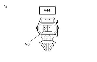
*a Component without harness connected
(Low Pressure Magnetic Valve)
Measure the voltage according to the value(s) in the table below.
Standard Voltage Tester Connection Condition Specified Condition A44-2 (VB) - Body ground Always 11 to 14 V Result Proceed to OK NG
NG
REPAIR OR REPLACE HARNESS OR CONNECTOR
OK
-
-
CHECK HARNESS AND CONNECTOR (LOW PRESSURE MAGNETIC VALVE - HEAT PUMP ECU ASSEMBLY)
-
Disconnect the A42 heat pump ECU assembly connector.
-
Measure the resistance according to the value(s) in the table below.
Standard Resistance Tester Connection Condition Specified Condition A44-1 (HPMV) - A42-23 (LPMV) Always Below 1 Ω A44-1 (HPMV) or A42-23 (LPMV) - Body ground Always 10 kΩ or higher Result Proceed to OK NG
NG
REPAIR OR REPLACE HARNESS OR CONNECTOR
OK
-
-
INSPECT HIGH PRESSURE MAGNETIC VALVE
-
Remove the high pressure magnetic valve.
-
Inspect the high pressure magnetic valve.
Result Proceed to OK NG
NG
REPLACE HIGH PRESSURE MAGNETIC VALVE Click here
OK
-
-
HIGH PRESSURE MAGNETIC VALVE (POWER SOURCE CIRCUIT)
-
Enter the following menus: Body Electrical / Air Conditioner / Active Test.
-
Perform the Active Test according to the display on the GTS.
Body Electrical > Air Conditioner > Active TestTester Display Measurement Item Control Range Diagnostic Note High Pressure Magnetic Valve High pressure magnetic valve OFF or ON -
Body Electrical > Air Conditioner > Active TestTester Display High Pressure Magnetic Valve -
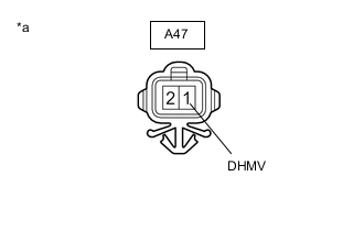
*a Component without harness connected
(High Pressure Magnetic Valve)
Measure the voltage according to the value(s) in the table below.
Standard Voltage Tester Connection Condition Specified Condition A47-1 (DHMV) - Body ground Always 11 to 14 V Result Proceed to OK NG
NG
REPAIR OR REPLACE HARNESS OR CONNECTOR
OK
-
-
CHECK HARNESS AND CONNECTOR (HIGH PRESSURE MAGNETIC VALVE - HEAT PUMP ECU ASSEMBLY)
-
Disconnect the A42 heat pump ECU assembly connector.
-
Measure the resistance according to the value(s) in the table below.
Standard Resistance Tester Connection Condition Specified Condition A47-2 (VD) - A42-2 (SOL-) Always Below 1 Ω A47-2 (VD) or A42-2 (SOL-) - Body ground Always 10 kΩ or higher Result Proceed to OK NG
NG
REPAIR OR REPLACE HARNESS OR CONNECTOR
OK
-
-
CHECK EVAPORATOR PRESSURE REGULATOR
-
Remove the evaporator pressure regulator.
-
Apply compressed air to the inlet port of the evaporator pressure regulator.
OK Air flows out of the outlet port. Result Proceed to OK NG
OK
REPLACE EVAPORATOR PRESSURE REGULATOR Click here
NG
PROCEED TO NEXT SUSPECTED AREA SHOWN IN PROBLEM SYMPTOMS TABLE Click here
-
-
CHECK ELECTRIC EXPANSION VALVE (COOLING)
-
Inspect the electric expansion valve (cooling).
Result Proceed to OK NG
OK
PROCEED TO NEXT SUSPECTED AREA SHOWN IN PROBLEM SYMPTOMS TABLE Click here
NG
REPLACE ELECTRIC EXPANSION VALVE (COOLING) Click here
-
-
INSPECT NO. 1 AIR CONDITIONING ACCESSORY ASSEMBLY (ELECTRIC EXPANSION VALVE (HEATING))
-
Turn the power switch on (READY).
-
Push the AUTO switch to operate the air conditioning system.
-
Turn the power switch off and wait for 2 minutes.
-
Remove the No. 1 air conditioning accessory assembly (electric expansion valve (heating)).
-
Apply compressed air to the inlet port of the No. 1 air conditioning accessory assembly (electric expansion valve (heating)).
OK Air flows out of the outlet port. Result Proceed to OK NG
OK
REPLACE NO. 1 AIR CONDITIONING ACCESSORY ASSEMBLY Click here
NG
-
-
CHECK HARNESS AND CONNECTOR (NO. 1 AIR CONDITIONING ACCESSORY ASSEMBLY (ELECTRIC EXPANSION VALVE (HEATING)) - HEAT PUMP ECU ASSEMBLY)
-
Disconnect the A42 heat pump ECU assembly connector.
-
Measure the resistance according to the value(s) in the table below.
Standard Resistance Tester Connection Condition Specified Condition A43-1 (VOL-) - A42-15 (AOR2) Always Below 1 Ω A43-4 (VOL+) - A42-16 (AOR1) Always Below 1 Ω A43-5 (TX+) - A42-35 (AOR4) Always Below 1 Ω A43-2 (TX-) - A42-36 (AOR3) Always Below 1 Ω A43-1 (VOL-) or A42-15 (AOR2) - Body ground Always 10 kΩ or higher A43-4 (VOL+) or A42-16 (AOR1) - Body ground Always 10 kΩ or higher A43-5 (TX+) or A42-35 (AOR4) - Body ground Always 10 kΩ or higher A43-2 (TX-) or A42-36 (AOR3) - Body ground Always 10 kΩ or higher Result Proceed to OK NG
NG
REPAIR OR REPLACE HARNESS OR CONNECTOR
OK
-
-
CHECK NO. 1 AIR CONDITIONING ACCESSORY ASSEMBLY (ELECTRIC EXPANSION VALVE (HEATING))
-
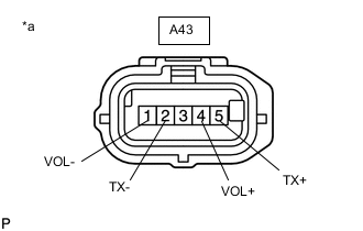
*a Component without harness connected
(No. 1 Air Conditioning Accessory Assembly (Electric Expansion Valve (Heating)))
Measure the resistance according to the value(s) in the table below.
Standard Resistance Tester Connection Condition Specified Condition A43-1 (VOL-) - A43-4 (VOL+) 20°C (68°F) 8 to 10 Ω A43-2 (TX-) - A43-5 (TX+) 20°C (68°F) 8 to 10 Ω Result Proceed to OK NG
OK
PROCEED TO NEXT SUSPECTED AREA SHOWN IN PROBLEM SYMPTOMS TABLE Click here
NG
REPLACE NO. 1 AIR CONDITIONING ACCESSORY ASSEMBLY Click here
-