AIR CONDITIONING SYSTEM TERMINALS OF ECU
-
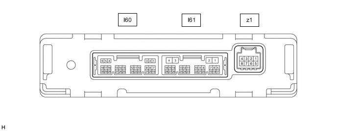
AIR CONDITIONING AMPLIFIER ASSEMBLY
Tech Tips
Check from the rear of the connector while it is connected to the air conditioning amplifier assembly.
Terminal No.
(Symbol)
Wiring Color Terminal Description Condition Specified Condition I60-1 (SG-1) - Body ground LG - Body ground Ground for cooler (room temp. sensor) thermistor Always Below 1 V I60-2 (SG-2) - Body ground P - Body ground Ground for thermistor assembly, air conditioner pressure sensor Always Below 1 V I60-6 (S5-3) - I60-2 (SG-2) GR - P Power supply for air conditioner pressure sensor Power switch on (IG) 4.75 to 5.25 V Power switch off Below 1 V I60-12 (CFAN) - I61-4 (GND) R - W-B Condenser fan relay control signal During remote air conditioning system operation Pulse generation I60-13 (TAM) - I60-2 (SG-2) BE - P Thermistor assembly signal
-
Power switch on (IG)
-
Ambient temperature: 25°C (77°F)
1.35 to 1.75 V
-
Power switch on (IG)
-
Ambient temperature: 40°C (104°F)
0.9 to 1.2 V I60-14 (TR) - I60-1 (SG-1) B - LG Cooler (room temp. sensor) thermistor signal
-
Power switch on (IG)
-
Cabin temperature: 25°C (77°F)
1.8 to 2.2 V
-
Power switch on (IG)
-
Cabin temperature: 40°C (104°F)
1.2 to 1.6 V I60-24 (PRE) - I60-2 (SG-2) SB - BE Air conditioner pressure sensor signal
-
Power switch on (READY)
-
Air conditioning system operating
-
Refrigerant pressure: Abnormal pressure (more than 3025 kPa (30.8 kgf/cm2, 439 psi))
4.61 V or higher
-
Power switch on (READY)
-
Air conditioning system operating
-
Refrigerant pressure: Abnormal pressure (less than 176 kPa (1.8 kgf/cm2, 26 psi))
Below 0.74 V
-
Power switch on (READY)
-
Air conditioning system operating
-
Refrigerant pressure: Normal pressure (less than 3025 kPa (30.8 kgf/cm2, 439 psi) and more than 176 kPa (1.8 kgf/cm2, 26 psi))
0.74 to 4.61 V I60-26 (SHIN) - I61-4 (GND) R - W-B Seat heater switch signal
-
Power switch on (IG)
-
Seat heater switch (for driver side) off
11 to 14 V
-
Power switch on (IG)
-
Seat heater switch (for driver side) on
Below 1 V I61-1 (B) - I61-4 (GND) V - W-B Power source (Back-up) Power switch off 11 to 14 V I61-2 (IG+) - I61-4 (GND) B - W-B Power source (IG) Power switch on (IG) 11 to 14 V Power switch off Below 1 V I61-4 (GND) - Body ground W-B - Body ground Ground for main power supply Always Below 1 V I61-6 (BLW) - I61-4 (GND) SB - W-B Blower motor speed control signal
-
Power switch on (IG)
-
Blower speed: LO
Pulse generation
(See waveform 1)
I61-11 (CANH) - I61-12 (CANL) BE - W CAN communication signal CAN communication is performed Pulse generation I61-13 (RLIN) - I61-4 (GND) G - W-B LIN communication signal (Heat pump ECU assembly) Power switch on (IG) Pulse generation I61-14 (LIN1) - I61-4 (GND) BE - W-B LIN communication signal (Air conditioning control assembly) Power switch on (IG) Pulse generation
(See waveform 2)
I61-15 (SCLI) - I61-4 (GND) G - W-B LIN communication signal (Air conditioning thermistor assembly*1, windshield wiper relay assembly*2) Power switch on (IG) Pulse generation I61-25 (SIG1) - I61-4 (GND) GR - W-B Power source (IG) Power switch on (IG) 11 to 14 V Power switch off Below 1 V z1-2 (BUS G) - Body ground - Ground for BUS IC Always Below 1 V z1-3 (BUS) - z1-2 (BUS G) - BUS IC control signal Power switch on (IG) Pulse generation
(See waveform 3)
z1-4 (B BUS) - z1-2 (BUS G) - Power supply for BUS IC Power switch off 11 to 14 V z1-5 (SGA) - Body ground - Ground for evaporator temperature sensor Always Below 1 V z1-6 (TEA) - z1-5 (SGA) - Evaporator temperature sensor signal
-
Power switch on (IG)
-
Evaporator temperature: 0°C (32°F)
1.7 to 2.1 V
-
Power switch on (IG)
-
Evaporator temperature: 15°C (59°F)
0.9 to 1.3 V
-
*1: w/ Humidity Sensor
-
*2: w/ Auto Wiper System
-
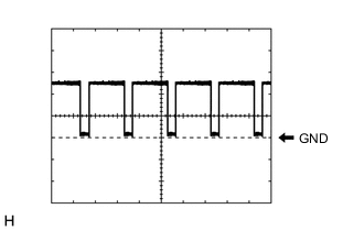
Waveform 1:
Item Content Terminal No. I61-6 (BLW) - I61-4 (GND) Tool Setting 2 V/DIV., 1 ms./DIV. Condition
-
Power switch on (IG)
-
Blower speed: LO
-
-
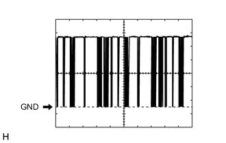
Waveform 2:
Item Content Terminal No. I61-14 (LIN1) - I61-4 (GND) Tool Setting 2 V/DIV., 20 ms./DIV. Condition Power switch on (IG) -
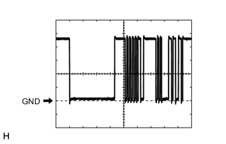
Waveform 3:
Item Content Terminal No. z1-3 (BUS) - z1-2 (BUS G) Tool Setting 2 V/DIV., 2 ms./DIV. Condition Power switch on (IG)
-
-
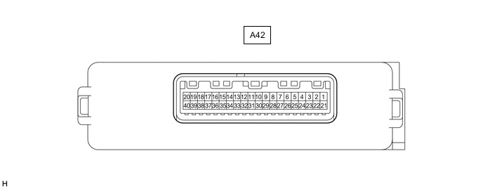
HEAT PUMP ECU ASSEMBLY
Tech Tips
Check from the rear of the connector while it is connected to the heat pump ECU assembly.
Terminal No.
(Symbol)
Wiring Color Terminal Description Condition Specified Condition A42-2 (SOL-) - A42-10 (RGND) B - W-B High pressure magnetic valve signal Active Test "High Pressure Magnetic Valve" OFF 11 to 14 V Active Test "High Pressure Magnetic Valve" ON Below 1 V A42-3 (TNG) - A42-10 (RGND) W - W-B No. 1 air conditioning accessory assembly (middle pressure magnetic valve) signal Active Test "Middle Pressure Magnetic Valve" OFF 11 to 14 V Active Test "Middle Pressure Magnetic Valve" ON Below 1 V A42-6 (TCHT) - A42-34 (TFG) LG - SB Discharge temperature sensor signal Power switch on (IG) 11 to 14 V Power switch off Below 1 V A42-7 (TPL) - A42-34 (TFG) P - SB Internal condenser temperature sensor signal Power switch on (IG) 11 to 14 V Power switch off Below 1 V A42-8 (DHMV) - A42-30 (SG-5) W - L Heat exchanger temperature sensor signal Power switch on (IG) 11 to 14 V Power switch off Below 1 V A42-9 (TPOR) - A42-30 (SG-5) V - L Evaporator pipe temperature sensor signal Power switch on (IG) 11 to 14 V Power switch off Below 1 V A42-10 (RGND) - Body ground W-B - Body ground Ground for magnetic valve Always Below 1 Ω A42-11 (FR) - A42-10 (RGND) G - W-B LIN communication signal (Heat pump ECU assembly) Power switch on (IG) Pulse generation
(See waveform 1)
A42-14 (GND2) - Body ground W-B - Body ground Ground for main power supply Always Below 1 Ω A42-15 (AOR2) - A42-10 (RGND) R - W-B No. 1 air conditioning accessory assembly (electric expansion valve (heating)) signal
-
Power switch on (IG)
-
Temperature setting: MAX HOT
-
Recirculation/fresh switch: RECIRCULATION
-
Blower speed: HI
-
Air outlet damper position: FOOT
Pulse generation
(See waveform 2)
A42-16 (AOR1) - A42-10 (RGND) W - W-B No. 1 air conditioning accessory assembly (electric expansion valve (heating)) signal
-
Power switch on (IG)
-
Temperature setting: MAX HOT
-
Recirculation/fresh switch: RECIRCULATION
-
Blower speed: HI
-
Air outlet damper position: FOOT
Pulse generation
(See waveform 2)
A42-18 (LBM1) - A42-10 (RGND) R - W-B Electric expansion valve (cooling) signal
-
Power switch on (IG)
-
Temperature setting: MAX COLD
-
Recirculation/fresh switch: RECIRCULATION
-
Blower speed: HI
-
Air outlet damper position: FACE
Pulse generation
(See waveform 3)
A42-19 (LBLO) - A42-10 (RGND) W - W-B Electric expansion valve (cooling) signal
-
Power switch on (IG)
-
Temperature setting: MAX COLD
-
Recirculation/fresh switch: RECIRCULATION
-
Blower speed: HI
-
Air outlet damper position: FACE
Pulse generation
(See waveform 3)
A42-20 (IG-1) - A42-14 (GND2) B - W-B Power source (IG) Power switch on (IG) 11 to 14 V Power switch off Below 1 V A42-23 (LPMV) - A42-10 (RGND) G - W-B Low pressure magnetic valve signal Active Test "Low Pressure Magnetic Valve" OFF 11 to 14 V Active Test "Low Pressure Magnetic Valve" ON Below 1 V A42-30 (SG-5) - Body ground L - Body ground Ground for evaporator pipe temperature sensor, heat exchanger temperature sensor Always Below 1 Ω A42-34 (TFG) - Body ground SB - Body ground Ground for internal condenser temperature sensor, discharge temperature sensor Always Below 1 Ω A42-35 (AOR4) - A42-10 (RGND) B - W-B No. 1 air conditioning accessory assembly (electric expansion valve (heating)) signal
-
Power switch on (IG)
-
Temperature setting: MAX HOT
-
Recirculation/fresh switch: RECIRCULATION
-
Blower speed: HI
-
Air outlet damper position: FOOT
Pulse generation
(See waveform 2)
A42-36 (AOR3) - A42-10 (RGND) G - W-B No. 1 air conditioning accessory assembly (electric expansion valve (heating)) signal
-
Power switch on (IG)
-
Temperature setting: MAX HOT
-
Recirculation/fresh switch: RECIRCULATION
-
Blower speed: HI
-
Air outlet damper position: FOOT
Pulse generation
(See waveform 2)
A42-38 (LBUT) - A42-10 (RGND) B - W-B Electric expansion valve (cooling) signal
-
Power switch on (IG)
-
Temperature setting: MAX COLD
-
Recirculation/fresh switch: RECIRCULATION
-
Blower speed: HI
-
Air outlet damper position: FACE
Pulse generation
(See waveform 3)
A42-39 (LBM2) - A42-10 (RGND) G - W-B Electric expansion valve (cooling) signal
-
Power switch on (IG)
-
Temperature setting: MAX COLD
-
Recirculation/fresh switch: RECIRCULATION
-
Blower speed: HI
-
Air outlet damper position: FACE
Pulse generation
(See waveform 3)
A42-40 (+B2) - A42-14 (GND2) R - W-B Power source (Back-up) Power switch off 11 to 14 V
-
Waveform 1:
Item Content Terminal No. A42-11 (FR) - A42-14 (GND2) Tool Setting 2 V/DIV., 2 ms./DIV. Condition Power switch on (IG) -
Waveform 2:
Item Content Terminal No.
-
A42-15 (AOR2) - A42-10 (RGND)
-
A42-16 (AOR1) - A42-10 (RGND)
-
A42-35 (AOR4) - A42-10 (RGND)
-
A42-36 (AOR3) - A42-10 (RGND)
Tool Setting 2 V/DIV., 2 ms./DIV. Condition
-
Power switch on (IG)
-
Temperature setting: MAX HOT
-
Recirculation/fresh switch: RECIRCULATION
-
Blower speed: HI
-
Air outlet damper position: FOOT
-
-
Waveform 3:
Item Content Terminal No.
-
A42-18 (LBM1) - A42-10 (RGND)
-
A42-19 (LBLO) - A42-10 (RGND)
-
A42-38 (LBUT) - A42-10 (RGND)
-
A42-39 (LBM2) - A42-10 (RGND)
Tool Setting 2 V/DIV., 2 ms./DIV. Condition
-
Power switch on (IG)
-
Temperature setting: MAX COLD
-
Recirculation/fresh switch: RECIRCULATION
-
Blower speed: HI
-
Air outlet damper position: FACE
-
-
-
AIR CONDITIONING CONTROL ASSEMBLY

Tech Tips
Check from the rear of the connector while it is connected to the air conditioning control assembly.
Terminal No.
(Symbol)
Wiring Color Terminal Description Condition Specified Condition I55-1 (GND) - Body ground W-B - Body ground Ground for air conditioning control assembly Always Below 1 V I55-4 (ILL+) - Body ground W - Body ground Illumination signal Light control switch off Below 1 V Light control switch in tail or head position 11 to 14 V I55-5 (ILL-) - Body ground V - Body ground Illumination signal Always Below 1 V I55-6 (LIN1) - Body ground BE - Body ground LIN communication signal Power switch on (IG) Pulse generation I55-8 (IG+) - I55-1 (GND) LG - W-B Power source (IG) Power switch off Below 1 V Power switch on (IG) 11 to 14 V -
HYBRID VEHICLE CONTROL ECU