AIR CONDITIONING SYSTEM SYSTEM DESCRIPTION
-
GENERAL
The air conditioning system has the following controls.
Control Outline Outlet Air Temperature Control Based on the temperature set by the temperature control dial, neural network control calculates outlet air temperature based on input signals from various sensors. Dual Control* The temperature settings for the driver and front passenger are controlled independently in order to provide separate vehicle interior temperatures for the right and left sides of the vehicle. Thus, air conditioning that accommodates the occupants' preferences has been realized. Blower Control Controls the blower motor in accordance with the airflow volume that has been calculated by neural network control based on input signals from various sensors. Air Outlet Control Automatically switches the air outlets in accordance with the outlet mode that has been calculated by neural network control. In accordance with the engine coolant temperature, ambient air temperature, amount of sunlight, required blower, outlet temperature and vehicle speed conditions, this control automatically switches the blower outlet to foot/defroster mode to prevent the windows from becoming fogged up when the ambient air temperature is low. Air Inlet Control Automatically controls the air inlet control damper to help achieve the calculated outlet air temperature that is required. Drives the air inlet control servo motor according to the operation of the air inlet control switch and moves the dampers to the fresh or recirculation position. Electric Inverter Compressor Control The air conditioning amplifier assembly calculates the target speed of the compressor based on the target evaporator temperature (which is calculated by the cooler (room temp. sensor) thermistor, thermistor assembly and automatic light control sensor) and the actual evaporator temperature that is detected by the evaporator temperature sensor in order to control the compressor speed. The air conditioning amplifier assembly calculates the target speed of the compressor based on the cabin condenser (condenser assembly) target temperature (which is calculated by the heat pump ECU assembly) and cabin condenser (condenser assembly) estimated temperature (which is calculated based on temperature and pressure information) in order to control the compressor speed. Turns the A/C on automatically when the AUTO button is pressed when the blower is on and the A/C is off. Decreases the compressor speed in order to ensure quietness when the vehicle is stopped or the engine is off. Ensured heating efficiency when heating using the heat pump cycle, even if the A/C switch is off, by keeping the compressor with motor assembly on. When the A/C switch is off, both parallel dehumidifying and series dehumidifying are not performed. Defroster Control Defroster control logic is used to improve defroster performance. S-FLOW Control When the S-FLOW switch is turned on, the air outlets operate in a front seat control mode. Rear Defogger Control Refer to Rear Defogger System.
ECO Mode Control When the pattern select switch assembly (drive mode switch) or air conditioning control assembly (ECO HEAT/COOL switch) is turned on, the air conditioning amplifier assembly limits the air conditioning system performance. Blower Customize* Allows the air volume to be adjusted in 3 levels using the air conditioning control assembly (AUTO FAST/ECO switch) during automatic air conditioning operation. Diagnosis A Diagnostic Trouble Code (DTC) is stored in memory when the air conditioning amplifier assembly detects a problem with the air conditioning system.
-
*: for Dual Type
-
-
MODE POSITION AND DAMPER OPERATION
Mode Position and Damper Operation.
Figure 1. for Dual Type
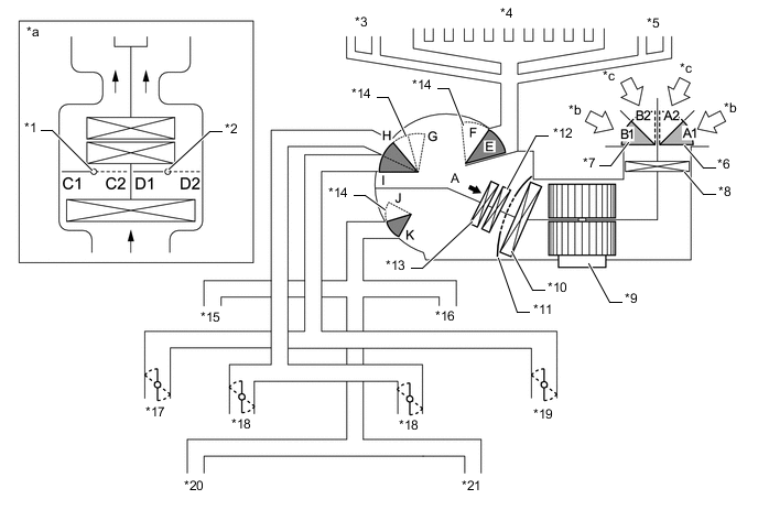
*1 Driver Side Air Mix Control Damper *2 Front Passenger Side Air Mix Control Damper *3 Driver Side Side Defroster *4 Front Defroster *5 Front Passenger Side Side Defroster *6 Air Inlet Control Damper (Lower Side) *7 Air Inlet Control Damper (Upper Side) *8 Clean Air Filter *9 Blower with Fan Motor Sub-assembly *10 No. 1 Cooler Evaporator Sub-assembly *11 Air Mix Control Damper *12 Heater Radiator Unit Sub-assembly *13 Internal Condenser *14 Mode Switching Damper *15 Driver Side Footwell Register *16 Front Passenger Side Footwell Register *17 Driver Side Side Register *18 Center Register *19 Front Passenger Side Side Register *20 Driver Side Rear Footwell Register *21 Front Passenger Side Rear Footwell Register - - *a View from A *b Recirculated Air *c Fresh Air - - Functions of Main Dampers Control Damper Operation Position Damper Position Operation Air Inlet Control Damper FRESH A1, B1 Allows fresh air to enter. RECIRCULATION A2, B2 Causes internal air to recirculate. Air Mix Control Damper Temperature Setting: 16°C (61°F) to 30°C (86°F) C1 - C2 Varies the front passenger side mixture ratio of the fresh air and the recirculation air in order to regulate the temperature continuously between hot and cold. D2 - D1 Varies the driver side mixture ratio of the fresh air and the recirculation air in order to regulate the temperature continuously between hot and cold. Air Outlet Control Damper DEF

F, H, K Defrosts the windshield through the center defroster, side defrosters and side registers. FOOT/DEF

F, H, J to K Defrosts the windshield through the center defroster, side defrosters and side registers, while air is also blown out from the front and rear footwell register ducts. FOOT

E, (E to F), H, J Air blows out of the front and rear footwell register ducts and side registers. In addition, air blows out slightly from the center defroster and side defrosters. B/L

E, G to I, J to K Air blows out of the center registers, side registers and front and rear footwell register ducts. FACE

E, G, K Air blows out of the center registers and side registers. Figure 2. for Single Type
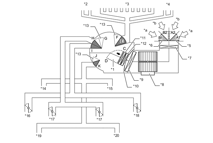
*1 Air Mix Control Damper *2 Driver Side Side Defroster *3 Front Defroster *4 Front Passenger Side Side Defroster *5 Air Inlet Control Damper (Lower Side) *6 Air Inlet Control Damper (Upper Side) *7 Clean Air Filter *8 Blower with Fan Motor Sub-assembly *9 No. 1 Cooler Evaporator Sub-assembly *10 Air Mix Control Damper *11 Internal Condenser *12 Heater Radiator Unit Sub-assembly *13 Mode Switching Damper *14 Driver Side Footwell Register *15 Front Passenger Side Footwell Register *16 Driver Side Side Register *17 Center Register *18 Front Passenger Side Side Register *19 Driver Side Rear Footwell Register *20 Front Passenger Side Rear Footwell Register *a Recirculated Air *b Fresh Air Functions of Main Dampers Control Damper Operation Position Damper Position Operation Air Inlet Control Damper FRESH A1, B1 Allows fresh air to enter. RECIRCULATION A2, B2 Causes internal air to recirculate. Air Mix Control Damper Temperature Setting: 16°C (61°F) to 30°C (86°F) C - D Varies the mixture ratio of the fresh air and the recirculation air in order to regulate the temperature continuously between hot and cold. Air Outlet Control Damper DEF
F, H, K Defrosts the windshield through the center defroster, side defrosters and side registers. FOOT/DEF
F, H, J to K Defrosts the windshield through the center defroster, side defrosters and side registers, while air is also blown out from the front and rear footwell register ducts. FOOT
E, (E to F), H, J Air blows out of the front and rear footwell register ducts and side registers. In addition, air blows out slightly from the center defroster and side defrosters. B/L
E, G to I, J to K Air blows out of the center registers, side registers and front and rear footwell register ducts. FACE
E, G, K Air blows out of the center registers and side registers. -
AIR OUTLETS AND AIRFLOW VOLUME
The size of each circle ○ indicates the ratio of airflow volume.
-
Air Outlets and Airflow Volume (for All Seat Control Modes).
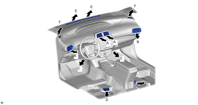
Mode FACE FOOT DEF Center Side Front Rear Center Side A B C D E F FACE


B/L


FOOT
FOOT/DEF
DEF
-
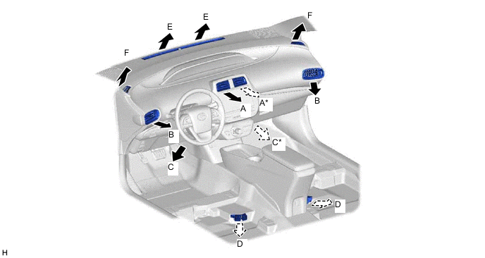
Air Outlets and Airflow Volume (for Front Seat Control Modes).
-
*: Airflow is stopped when the front passenger seat is not occupied.
Mode FACE FOOT DEF Center Side Front Rear Center Side A B C D E F FACE
B/L
FOOT
FOOT/DEF
DEF
-
-
-
OUTLINE OF REMOTE AIR CONDITIONING SYSTEM
-
When the remote A/C switch on the electrical key transmitter sub-assembly is operated, the air conditioning system wi'll be operated automatically for up to 10 minutes using a charging cable or the HV battery as a power supply.
Tech Tips
-
When a charging cable is connected, the remote air conditioning system wi'll operate using the HV battery or external power supply.
-
When a charging cable is not connected, the remote air conditioning system wi'll operate using only the HV battery.
Operating Condition Item Condition Power switch condition Power switch off 3 minutes and 30 seconds or more after power switch turned off Power switch not pressed 2.5 seconds or more after power switch turned off Theft deterrent system condition Not in alarm sounding state Door courtesy light switch condition All doors closed Hood closed Door lock condition All doors are locked or in lockable state Tech Tips
If an operating condition is no longer met while the remote air conditioning system is operating, operation will be suspended.
-
-
Each component of the remote air conditioning system has the functions described in the table.
Function of Main Components Component Outline Electrical key transmitter sub-assembly Sends remote air conditioning system on/off signals to the certification ECU (smart key ECU assembly). Electric vehicle charger assembly Sends remote air conditioning system on/off signals to the air conditioning amplifier assembly when a charging cable is connected to the vehicle. Certification ECU (smart key ECU assembly)
-
Receives a signal from the electrical key transmitter sub-assembly.
-
Sends a signal to the main body ECU (multiplex network body ECU).
-
Controls the remote air conditioning system power supply.
Main body ECU (multiplex network body ECU)
-
Checks the alarm state of the theft deterrent system.
-
When the remote air conditioning system starts:
-
Locks all of the doors.
-
Checks that all of the doors are closed and locked.
-
Checks that the hood is closed.
-
Checks the power switch status.
Hybrid vehicle control ECU
-
Receives the operation, suspension, blower outlet and set temperature signals of the remote air conditioning system.
-
Checks if park (P) is selected.
-
Permits remote air conditioning system operation.
-
Checks if an electric vehicle charger cable assembly is connected to the vehicle (plug-in charging permitted).
-
Starts/stops the hybrid system.
Air conditioning amplifier assembly
-
Receives the operation, suspension, blower outlet and set temperature signals of the remote air conditioning system.
-
Operates the compressor with motor assembly.
-
Judges when to stop the remote air conditioning system.
-
Sends the hybrid system start request signal to the hybrid vehicle control ECU.
-
Sends the pre air conditioning mode signal to the main body ECU (multiplex network body ECU).
-
-
-
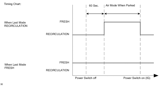
PARKING FRESH CONTROL
When 60 seconds have elapsed since the power switch has been turned off, the air conditioning amplifier assembly uses control logic which automatically changes the air inlet to FRESH mode to purge undesired odors from the air conditioning unit.
This logic will therefore reduce undesired odors upon starting the air conditioning system.
-
COMPRESSOR WITH MOTOR ASSEMBLY
Tech Tips
In order to ensure the proper insulation of the internal high-voltage portion of the compressor and the compressor housing, this vehicle has adopted a compressor oil (ND-OIL 11) with a high level of insulation performance. Therefore, never use a compressor oil other than ND-OIL 11 type compressor oil or equivalent.
-
An ESBG27 type compressor with motor assembly that is driven by a motor is used. The basic construction and operation of this compressor are the same as an ordinary scroll compressor, except that it is driven by an electric motor.
-
The compressor with motor assembly consists of a spirally wound fixed scroll and rotating scroll that from a pair, an injection block, brushless motor, oil separator, motor shaft and air conditioning inverter.
-
An air conditioning inverter is integrated with the compressor with motor assembly. This inverter operates the compressor on HV battery voltage. As a result, the air conditioning system is actuated without depending on the operation of the engine, thus realizing a comfortable air conditioning system and low fuel consumption.
-
The fixed scroll is integrated with the housing. Because the rotation of the shaft causes the rotating scroll to revolve while maintaining the same posture, the volume of the space that is partitioned by both scrolls varies to perform the suction, compression and the discharge of the refrigerant gas. Locating the suction port directly above the scrolls enables direct suction, thus realizing improved suction efficiency. Containing a built-in oil separator, the compressor is able to separate the compressor oil that is intermixed with the refrigerant and circulates in the refrigerant cycle, thus realizing a reduction in the oil circulation rate.
-
Low-moisture permeation hoses are used for the suction and discharge hoses of the compressor in order to minimize the entry of moisture into the refrigerant cycle.
-
-
EVAPORATOR TEMPERATURE SENSOR
The evaporator temperature sensor detects the temperature of the cool air immediately after the evaporator in the form of resistance changes, and outputs it to the air conditioning amplifier assembly.
-
BLOWER MOTOR WITH FAN SUB-ASSEMBLY
The blower motor has a built-in blower controller, and is controlled using duty control performed by the air conditioning amplifier assembly.
-
BUS CONNECTOR (AIR CONDITIONING HARNESS ASSEMBLY)
-
Bus connectors are used in the wire harness that connects the servo motors to the air conditioning amplifier assembly.
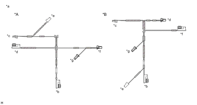
*A for LHD *B for RHD *a Example *b Bus Connector
(to No. 1 Air Conditioning Radiator Damper Servo Sub-assembly)
*c Bus Connector
(to No. 2 Air Conditioning Radiator Damper Servo Sub-assembly)
*d Bus Connector
(to No. 3 Air Conditioning Radiator Damper Servo Sub-assembly)
*e Bus Connector
(to No. 1 Blower Damper Servo Sub-assembly)
*f to Air Conditioning Amplifier Assembly *g to Evaporator Temperature Sensor - - -
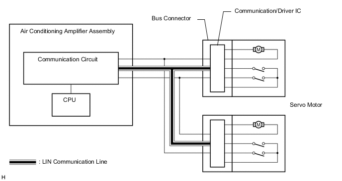
Each bus connector has a built-in communication/driver IC which communicates with the air conditioning amplifier assembly, actuates the servo motor, and has a position detection function. This enables bus communication for the servo motor wire harness, for a more lightweight construction and a reduced number of wires.
-
-
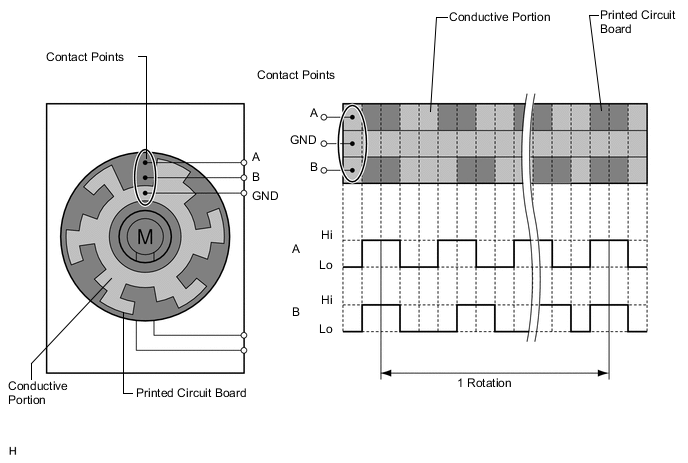
SERVO MOTOR
A pulse pattern type servo motor consists of a printed circuit board and a servo motor. The printed circuit board has three contact points, and can transmit two ON-OFF signals to the air conditioning amplifier assembly based on the difference of the pulse phases. The bus connector can detect the damper position and movement direction with these signals.
-
AIR CONDITIONING THERMISTOR ASSEMBLY (w/ Humidity Sensor)
The air conditioning thermistor assembly detects the amount of raindrops on the windshield glass, the temperature of the windshield glass, and the temperature and humidity around the windshield glass and sends signals to the air conditioning amplifier assembly.
-
COOLER (ROOM TEMP. SENSOR) THERMISTOR
The cooler (room temp. sensor) thermistor detects the cabin temperature based on changes in the resistance of its built-in thermistor and sends a signal to the air conditioning amplifier assembly.
-
THERMISTOR ASSEMBLY
The thermistor assembly detects the outside temperature based on changes in the resistance of its built-in thermistor and sends a signal to the air conditioning amplifier assembly.
-
AUTOMATIC LIGHT CONTROL SENSOR
The automatic light control sensor detects (in the form of changes in the current that flows through the built-in photo diode) the changes in the amount of sunlight and outputs these sunlight strength signals to the air conditioning amplifier assembly.
-
AIR CONDITIONER PRESSURE SENSOR
The air conditioner pressure sensor detects the refrigerant pressure and outputs it to the air conditioning amplifier assembly in the form of voltage changes.