AIR CONDITIONING SYSTEM, Diagnostic DTC:B1382
| DTC Code | DTC Name |
|---|---|
| B1382 | Evaporator Refrigerant Temperature Sensor Circuit |
DESCRIPTION
The evaporator pipe temperature sensor is installed to the outlet pipe of the No. 1 cooler evaporator sub-assembly and detects the refrigerant temperature for heat pump air-conditioning control. The resistance of the evaporator pipe temperature sensor changes depending on the refrigerant temperature of the No. 1 cooler evaporator sub-assembly outlet. When the temperature becomes low, the resistance of the thermistor increases. When the temperature becomes high, the resistance decreases.
The heat pump ECU assembly applies a voltage (5 V) to the evaporator pipe temperature sensor and reads voltage changes due to changes in the resistance of the evaporator pipe temperature sensor.
| DTC No. | Detection Item | DTC Detection Condition | Trouble Area | Memory |
|---|---|---|---|---|
| B1382 | Evaporator Refrigerant Temperature Sensor Circuit | Open or short in evaporator pipe temperature sensor circuit |
|
Memorized (4 sec. or more)* |
-
*: The heat pump ECU assembly stores this DTC if the malfunction has occurred for the period of time indicated in the brackets.
WIRING DIAGRAM
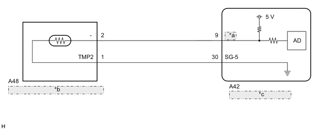
| *a | TPOR |
| *b | Evaporator Pipe Temperature Sensor |
| *c | Heat Pump ECU Assembly |
PROCEDURE
-
CHECK FOR DTC
-
Check for DTCs.
Body Electrical > Air Conditioner > Trouble CodesResult Result Proceed to DTC B1380 is output A DTC B1380, B1382 are output B
B 
CHECK HARNESS AND CONNECTOR (EVAPORATOR PIPE TEMPERATURE SENSOR - HEAT PUMP ECU ASSEMBLY) Click here
A 
-
-
INSPECT EVAPORATOR PIPE TEMPERATURE SENSOR
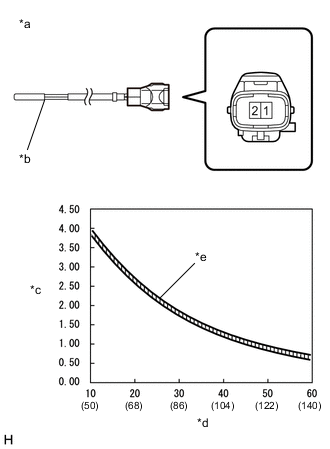
*a Component without harness connected
(Evaporator Pipe Temperature Sensor)
*b Sensing Portion *c Resistance (kΩ) *d Temperature (°C (°F)) *e Allowable Range
-
Remove the evaporator pipe temperature sensor.
-
Measure the resistance according to the value(s) in the table below.
Standard Resistance Tester Connection Condition Specified Condition 1 (TMP2) - 2 (-) 10°C (50°F) 3.87 to 3.96 kΩ 15°C (59°F) 3.15 to 3.23 kΩ 20°C (68°F) 2.57 to 2.66 kΩ 25°C (77°F) 2.12 to 2.20 kΩ 30°C (86°F) 1.75 to 1.83 kΩ 35°C (95°F) 1.46 to 1.53 kΩ 40°C (104°F) 1.22 to 1.29 kΩ 45°C (113°F) 1.03 to 1.09 kΩ 50°C (122°F) 0.87 to 0.92 kΩ 55°C (131°F) 0.74 to 0.78 kΩ 60°C (140°F) 0.63 to 0.67 kΩ Note
-
Hold the sensor only by its connector. Touching the sensing portion may change the resistance value.
-
When measuring, the sensor temperature must be the same as the ambient temperature.
Tech Tips
As the temperature increases, the resistance decreases (see the graph).
Result Proceed to OK NG -
NG 
REPLACE EVAPORATOR PIPE TEMPERATURE SENSOR Click here
OK
-
-
CHECK HARNESS AND CONNECTOR (EVAPORATOR PIPE TEMPERATURE SENSOR - HEAT PUMP ECU ASSEMBLY)
-
Disconnect the A42 heat pump ECU assembly connector.
-
Measure the resistance according to the value(s) in the table below.
Standard Resistance Tester Connection Condition Specified Condition A48-2 (-) - A42-9 (TPOR) Always Below 1 Ω A48-2 (-) or A42-9 (TPOR) - Body ground Always 10 kΩ or higher Result Proceed to OK NG
OK
REPLACE HEAT PUMP ECU ASSEMBLY Click here
NG
REPAIR OR REPLACE HARNESS OR CONNECTOR
-
-
CHECK HARNESS AND CONNECTOR (EVAPORATOR PIPE TEMPERATURE SENSOR - HEAT PUMP ECU ASSEMBLY)
-
Disconnect the A48 evaporator pipe temperature sensor connector.
-
Disconnect the A42 heat pump ECU assembly connector.
-
Measure the resistance according to the value(s) in the table below.
Standard Resistance Tester Connection Condition Specified Condition A48-1 (TMP2) - A42-30 (SG-5) Always Below 1 Ω A48-1 (TMP2) or A42-30 (SG-5) - Body ground Always 10 kΩ or higher Result Proceed to OK NG
OK
REPLACE HEAT PUMP ECU ASSEMBLY Click here
NG
REPAIR OR REPLACE HARNESS OR CONNECTOR
-