AIR CONDITIONING SYSTEM, Diagnostic DTC:B1384
| DTC Code | DTC Name |
|---|---|
| B1384 | Heating Electric Expansion Valve Circuit |
DESCRIPTION
The No. 1 air conditioning accessory assembly (electric expansion valve (heating)) is installed to the accumulator and accessory assembly and is partially open when the power switch is off. When the power switch is on (IG), the heat pump air-conditioning control operates the stepping motor and adjusts the opening amount of the No. 1 air conditioning accessory assembly (electric expansion valve (heating)). When the heat pump air-conditioning control is in cooling mode, the No. 1 air conditioning accessory assembly (electric expansion valve (heating)) is open based on the signal from the heat pump ECU assembly. When the heat pump air-conditioning control is in series heating/parallel heating/heating/gas injection heating mode, the No. 1 air conditioning accessory assembly (electric expansion valve (heating)) is adjusted to optimally control the opening amount based on the signal from the heat pump ECU assembly.
| DTC No. | Detection Item | DTC Detection Condition | Trouble Area | Memory |
|---|---|---|---|---|
| B1384 | Heating Electric Expansion Valve Circuit | When the motor is being operated, there is an open or short in the No. 1 air conditioning accessory assembly (electric expansion valve (heating)) circuit or the No. 1 air conditioning accessory assembly (electric expansion valve (heating)) is overheating |
|
Memorized (4 sec. or more)* |
-
*: The heat pump ECU assembly stores this DTC if the malfunction has occurred for the period of time indicated in the brackets.
WIRING DIAGRAM
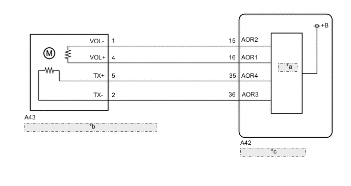
| *a | Driver IC |
| *b | No. 1 Air Conditioning Accessory Assembly (Electric Expansion Valve (Heating)) |
| *c | Heat Pump ECU Assembly |
PROCEDURE
-
CHECK HARNESS AND CONNECTOR (NO. 1 AIR CONDITIONING ACCESSORY ASSEMBLY (ELECTRIC EXPANSION VALVE (HEATING)) - HEAT PUMP ECU ASSEMBLY)
-
Disconnect the A43 No. 1 air conditioning accessory assembly (electric expansion valve (heating)) connector.
-
Disconnect the A42 heat pump ECU assembly connector.
-
Measure the resistance according to the value(s) in the table below.
Standard Resistance Tester Connection Condition Specified Condition A43-1 (VOL-) - A42-15 (AOR2) Always Below 1 Ω A43-4 (VOL+) - A42-16 (AOR1) Always Below 1 Ω A43-5 (TX+) - A42-35 (AOR4) Always Below 1 Ω A43-2 (TX-) - A42-36 (AOR3) Always Below 1 Ω A43-1 (VOL-) or A42-15 (AOR2) - Body ground Always 10 kΩ or higher A43-4 (VOL+) or A42-16 (AOR1) - Body ground Always 10 kΩ or higher A43-5 (TX+) or A42-35 (AOR4) - Body ground Always 10 kΩ or higher A43-2 (TX-) or A42-36 (AOR3) - Body ground Always 10 kΩ or higher Result Proceed to OK NG
NG 
REPAIR OR REPLACE HARNESS OR CONNECTOR
OK 
-
-
INSPECT NO. 1 AIR CONDITIONING ACCESSORY ASSEMBLY (ELECTRIC EXPANSION VALVE (HEATING))
-
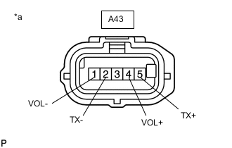
*a Component without harness connected
(No. 1 air conditioning accessory assembly (electric expansion valve (heating)))
Measure the resistance according to the value(s) in the table below.
Standard Resistance Tester Connection Condition Specified Condition A43-1 (VOL-) - A43-4 (VOL+) 20°C (68°F) 8 to 10 Ω A43-2 (TX-) - A43-5 (TX+) 20°C (68°F) 8 to 10 Ω Result Proceed to OK NG
OK
REPLACE HEAT PUMP ECU ASSEMBLY Click here
NG
REPLACE NO. 1 AIR CONDITIONING ACCESSORY ASSEMBLY (ELECTRIC EXPANSION VALVE (HEATING)) Click here
-