AIR CONDITIONING SYSTEM, Diagnostic DTC:B1442/42
| DTC Code | DTC Name |
|---|---|
| B1442/42 | Air Inlet Damper Control Servo Motor Circuit |
DESCRIPTION
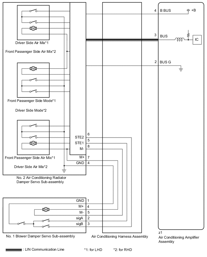
The No. 1 blower damper servo sub-assembly sends pulse signals to inform the air conditioning amplifier assembly of the damper position. The air conditioning amplifier assembly activates the motor (normal or reverse) based on these signals to move the air inlet damper to the appropriate position to change the air inlet mode (fresh, recirculation/fresh, and recirculation).
The air conditioning amplifier assembly communicates with the servo through a communication/driver IC and wiring assembly called the air conditioning harness assembly.
| DTC No. | Detection Item | DTC Detection Condition | Trouble Area | Memory |
|---|---|---|---|---|
| B1442/42 | Air Inlet Damper Control Servo Motor Circuit | Air inlet damper position sensor value does not change even if air conditioning amplifier assembly operates No. 1 blower damper servo sub-assembly |
|
Memorized (30 sec. or more)* |
-
*: The air conditioning amplifier assembly stores this DTC if the malfunction has occurred for the period of time indicated in the brackets.
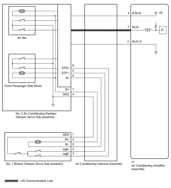
WIRING DIAGRAM
-
for Dual Type
-
for Single Type
CAUTION / NOTICE / HINT
Tech Tips
-
Confirm that no mechanical problem is present because this DTC can be output when either a damper link or damper is mechanically locked.
-
When installing the damper servo motor, make sure to install it correctly.
PROCEDURE
-
CONFIRM MODEL
-
Choose the model to be inspected.
Result Result Proceed to for LHD (for Dual Type) A for LHD (for Single Type) B for RHD C
B 
CHECK FOR DTC Click here
C
CHECK FOR DTC Click here
A 
-
-
CHECK FOR DTC
-
Check for DTCs.
Body Electrical > Air Conditioner > Trouble CodesResult Result Proceed to DTC B1497/97 is output A DTC B1441/41, B1442/42, B1446/46 and B1448/48 are output B DTC B1442/42 is output C
A 
GO TO DTC B1497/97 Click here
B
REPLACE NO. 2 AIR CONDITIONING RADIATOR DAMPER SERVO SUB-ASSEMBLY Click here
C
GO TO STEP 5 Click here
-
-
CHECK FOR DTC
-
Check for DTCs.
Body Electrical > Air Conditioner > Trouble CodesResult Result Proceed to DTC B1497/97 is output A DTC B1441/41, B1442/42, and B1448/48 are output B DTC B1442/42 is output C
A
GO TO DTC B1497/97 Click here
B
REPLACE NO. 2 AIR CONDITIONING RADIATOR DAMPER SERVO SUB-ASSEMBLY Click here
C
GO TO STEP 5 Click here
-
-
CHECK FOR DTC
-
Check for DTCs.
Body Electrical > Air Conditioner > Trouble CodesResult Result Proceed to DTC B1497/97 is output A DTC B1441/41, B1442/42, B1443/43 and B1446/46 are output B DTC B1442/42 is output C
A
GO TO DTC B1497/97 Click here
B
REPLACE NO. 2 AIR CONDITIONING RADIATOR DAMPER SERVO SUB-ASSEMBLY Click here
C
-
-
INSPECT BLOWER ASSEMBLY
-
Remove the No. 1 blower damper servo sub-assembly.
-
Operate the air inlet control dampers by hand.
OK The air inlet control dampers are easily operated by hand. Result Proceed to OK NG
NG
REPLACE BLOWER ASSEMBLY Click here
OK
-
-
INSPECT AIR CONDITIONING HARNESS ASSEMBLY
-
Disconnect the No. 2 air conditioning radiator damper servo sub-assembly connector.
-
Disconnect the No. 1 blower damper servo sub-assembly connector.
-
Measure the resistance according to the value(s) in the table below.
Standard Resistance Tester Connection Condition Specified Condition 6 (STE2) - 3 (sigB) Always Below 1 Ω 5 (STE1) - 2 (sigA) Always Below 1 Ω 8 (M-) - 5 (M-) Always Below 1 Ω 7 (M+) - 4 (M+) Always Below 1 Ω 4 (GND) - 1 (GND) Always Below 1 Ω 6 (STE2) or 3 (sigB) - Body ground Always 10 kΩ or higher 5 (STE1) or 2 (sigA) - Body ground Always 10 kΩ or higher 8 (M-) or 5 (M-) - Body ground Always 10 kΩ or higher 7 (M+) or 4 (M+) - Body ground Always 10 kΩ or higher Result Proceed to OK NG
NG
REPLACE AIR CONDITIONING HARNESS ASSEMBLY Click here
OK
-
-
PERFORM ACTIVE TEST USING GTS
-
Reconnect the No. 2 air conditioning radiator damper servo sub-assembly connector.
-
Remove the No. 3 air conditioning radiator damper servo sub-assembly.
-
Connect the No. 1 blower damper servo sub-assembly connector to the No. 3 air conditioning radiator damper servo sub-assembly.
-
Connect the GTS to the DLC3.
-
Turn the power switch on (IG).
-
Turn the GTS on.
-
Enter the following menus: Body Electrical / Air Conditioner / Active Test.
-
Perform the Active Test according to the display on the GTS.
Body Electrical > Air Conditioner > Active TestTester Display Measurement Item Control Range Diagnostic Note Air Inlet Damper Targ Pulse No. 1 blower damper servo sub-assembly pulse* Min.: 128
Max.: 383
Operates between 220 to 256 pulses
-
*: Thus this Active Test is for the No. 1 blower damper servo sub-assembly, in this case it is used to check the operation of the No. 3 air conditioning radiator damper servo sub-assembly.
Body Electrical > Air Conditioner > Active TestTester Display Air Inlet Damper Targ Pulse OK The No. 3 air conditioning radiator damper servo sub-assembly operates. Result Proceed to OK NG -
OK
REPLACE NO. 1 BLOWER DAMPER SERVO SUB-ASSEMBLY Click here
NG
REPLACE NO. 2 AIR CONDITIONING RADIATOR DAMPER SERVO SUB-ASSEMBLY Click here
-