AIR CONDITIONING SYSTEM, Diagnostic DTC:B1380
| DTC Code | DTC Name |
|---|---|
| B1380 | External Condenser Refrigerant Temperature Sensor Circuit |
DESCRIPTION
The heat exchanger temperature sensor is installed to the outlet pipe of the cooler condenser assembly and detects the refrigerant temperature for heat pump air-conditioning control. The resistance of the heat exchanger temperature sensor changes depending on the refrigerant temperature of the cooler condenser assembly outlet. When the temperature becomes low, the resistance of the thermistor increases. When the temperature becomes high, the resistance decreases.
The heat pump ECU assembly applies a voltage (5 V) to the heat exchanger temperature sensor and reads voltage changes due to changes in the resistance of the heat exchanger temperature sensor.
| DTC No. | Detection Item | DTC Detection Condition | Trouble Area | Memory |
|---|---|---|---|---|
| B1380 | External Condenser Refrigerant Temperature Sensor Circuit | Open or short in heat exchanger temperature sensor circuit |
|
Memorized (4 sec. or more)* |
-
*: The heat pump ECU assembly stores this DTC if the malfunction has occurred for the period of time indicated in the brackets.
WIRING DIAGRAM
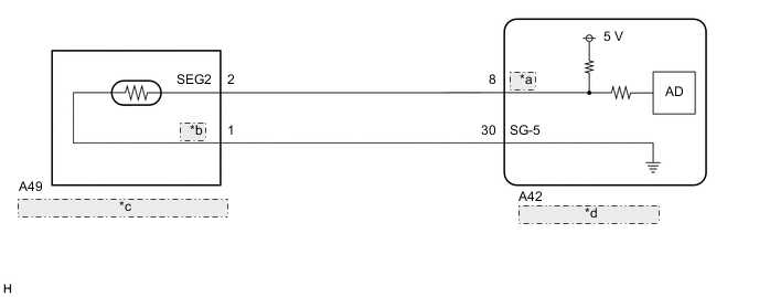
| *a | DHMV |
| *b | TCLT |
| *c | Heat Exchanger Temperature Sensor |
| *d | Heat Pump ECU Assembly |
PROCEDURE
-
CHECK FOR DTC
-
Check for DTCs.
Body Electrical > Air Conditioner > Trouble CodesResult Result Proceed to DTC B1380 is output A DTC B1380, B1382 are output B
B 
CHECK HARNESS AND CONNECTOR (HEAT EXCHANGER TEMPERATURE SENSOR - HEAT PUMP ECU ASSEMBLY) Click here
A 
-
-
INSPECT HEAT EXCHANGER TEMPERATURE SENSOR
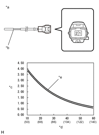
*a Component without harness connected
(Heat Exchanger Temperature Sensor)
*b Sensing Portion *c Resistance (kΩ) *d Temperature (°C (°F)) *e Allowable Range
-
Remove the heat exchanger temperature sensor.
-
Measure the resistance according to the value(s) in the table below.
Standard Resistance Tester Connection Condition Specified Condition 1 (TCLT) - 2 (SEG2) 10°C (50°F) 3.87 to 3.96 kΩ 15°C (59°F) 3.15 to 3.23 kΩ 20°C (68°F) 2.57 to 2.66 kΩ 25°C (77°F) 2.12 to 2.20 kΩ 30°C (86°F) 1.75 to 1.83 kΩ 35°C (95°F) 1.46 to 1.53 kΩ 40°C (104°F) 1.22 to 1.29 kΩ 45°C (113°F) 1.03 to 1.09 kΩ 50°C (122°F) 0.87 to 0.92 kΩ 55°C (131°F) 0.74 to 0.78 kΩ 60°C (140°F) 0.63 to 0.67 kΩ Note
-
Hold the sensor only by its connector. Touching the sensing portion may change the resistance value.
-
When measuring, the sensor temperature must be the same as the ambient temperature.
Tech Tips
As the temperature increases, the resistance decreases (see the graph).
Result Proceed to OK NG -
NG 
REPLACE HEAT EXCHANGER TEMPERATURE SENSOR Click here
OK
-
-
CHECK HARNESS AND CONNECTOR (HEAT EXCHANGER TEMPERATURE SENSOR - HEAT PUMP ECU ASSEMBLY)
-
Disconnect the A42 heat pump ECU assembly connector.
-
Measure the resistance according to the value(s) in the table below.
Standard Resistance Tester Connection Condition Specified Condition A49-2 (SEG2) - A42-8 (DHMV) Always Below 1 Ω A49-2 (SEG2) or A42-8 (DHMV) - Body ground Always 10 kΩ or higher Result Proceed to OK NG
OK
REPLACE HEAT PUMP ECU ASSEMBLY Click here
NG
REPAIR OR REPLACE HARNESS OR CONNECTOR
-
-
CHECK HARNESS AND CONNECTOR (HEAT EXCHANGER TEMPERATURE SENSOR - HEAT PUMP ECU ASSEMBLY)
-
Disconnect the A49 heat exchanger temperature sensor connector.
-
Disconnect the A42 heat pump ECU assembly connector.
-
Measure the resistance according to the value(s) in the table below.
Standard Resistance Tester Connection Condition Specified Condition A49-1 (TCLT) - A42-30 (SG-5) Always Below 1 Ω A49-1 (TCLT) or A42-30 (SG-5) - Body ground Always 10 kΩ or higher Result Proceed to OK NG
OK
REPLACE HEAT PUMP ECU ASSEMBLY Click here
NG
REPAIR OR REPLACE HARNESS OR CONNECTOR
-