SEAT BELT WARNING SYSTEM(w/ Occupant Classification System) TERMINALS OF ECU
-
CHECK MAIN BODY ECU (MULTIPLEX NETWORK BODY ECU) AND INSTRUMENT PANEL JUNCTION BLOCK ASSEMBLY
-
Disconnect the instrument panel junction block assembly and main body ECU (multiplex network body ECU) connectors.
-
Reconnect the instrument panel junction block assembly connectors.
-
Measure the resistance and voltage according to the value(s) in the table below.
Tech Tips
Measure the values on the wire harness side with the connector disconnected.
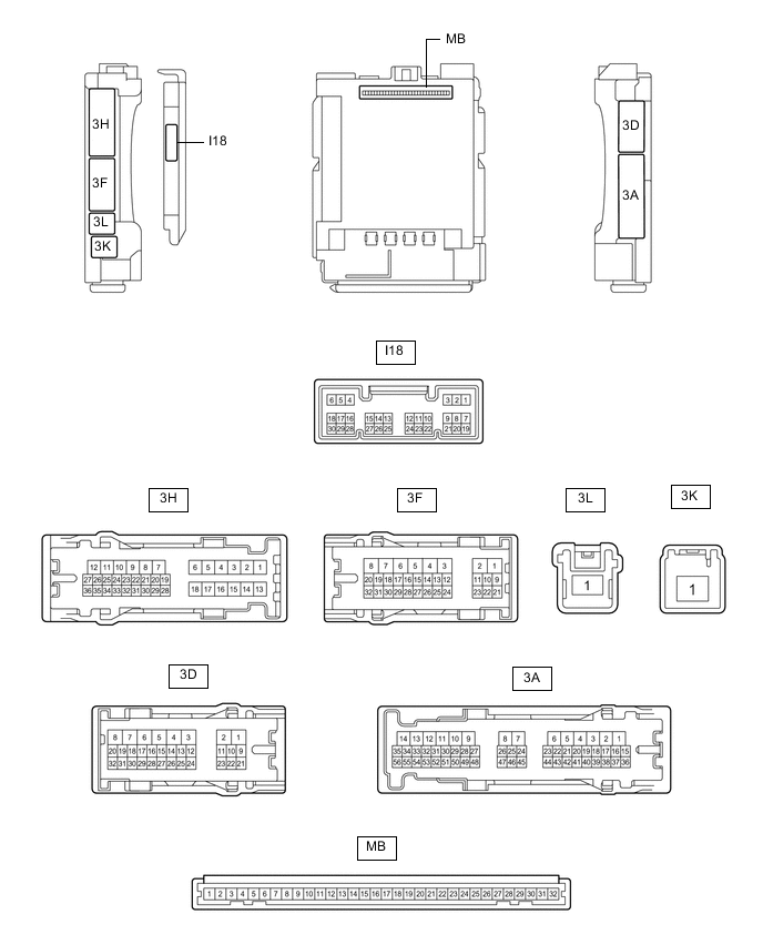
Terminal No. (Symbol) Wiring Color Terminal Description Condition Specified Condition MB-31 (BECU) - Body ground - Auxiliary battery power supply Power switch off 11 to 14 V MB-32 (IG) - Body ground - Ignition power supply (IG signal) Power switch on (IG) → off 11 to 14 V → Below 1 V MB-30 (ACC) - Body ground - Ignition power supply (ACC signal) Power switch on (ACC) → off 11 to 14 V → Below 1 V MB-11 (GND1) - Body ground - Ground Always Below 1 Ω MB-2 (RCTY) - Body ground - Rear door courtesy light switch RH input Rear door LH closed (OFF) 10 kΩ or higher Rear door LH open (ON) Below 1 Ω MB-13 (LCTY) - Body ground - Rear door courtesy light switch LH input Rear door RH closed (OFF) 10 kΩ or higher Rear door RH open (ON) Below 1 Ω
-
-
CHECK COMBINATION METER ASSEMBLY
-
Disconnect the I6 combination meter assembly connector.
-
Measure the voltage and resistance according to the value(s) in the table below.
Tech Tips
Measure the values on the wire harness side with the connector disconnected.
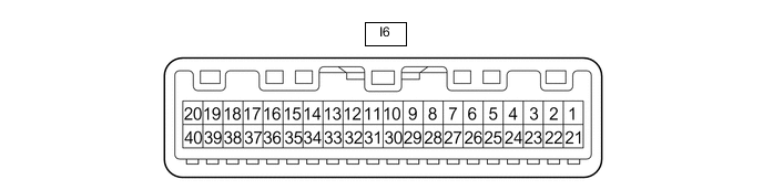
Terminal No. (Symbol) Wiring Color Terminal Description Condition Specified Condition I6-22 (B) - Body ground W - Body ground Auxiliary battery power supply Power switch off 11 to 14 V I6-21 (IG+) - Body ground G - Body ground Ignition power supply Power switch off Below 1 V Power switch on (IG) 11 to 14 V I6-28 (ES) - Body ground W-B - Body ground Ground Always Below 1 Ω I6-12 (RLSB) - Body ground GR - Body ground Rear LH seat belt buckle switch signal Rear LH seat belt fastened 10 kΩ or higher Rear LH seat belt unfastened Below 1 Ω I6-10 (RRSB) - Body ground P - Body ground Rear RH seat belt buckle switch signal Rear RH seat belt fastened 10 kΩ or higher Rear RH seat belt unfastened Below 1 Ω
-
-
CHECK AIRBAG ECU ASSEMBLY
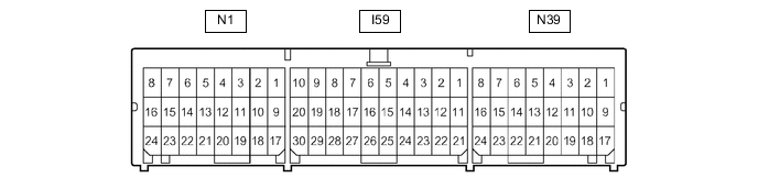
Terminal No. Terminal Symbol Destination N1-10 LBE+ Front seat inner belt assembly LH N1-18 LBE- Front seat inner belt assembly LH -
CHECK OCCUPANT DETECTION ECU

-
Measure the voltage and check for pulses according to the value(s) in the table below.
Terminal No. (Symbol) Wiring Color Terminal Description Condition Specified Condition a5-10 (GND) - Body ground W-B - Body ground Ground Always Below 1 V a5-6 (IG2) - a5-10 (GND) B - W-B Power source Power switch on (IG) 11 to 14 V a5-9 (BGND) - a5-10 (GND) P - W-B Front passenger buckle switch ground Always Below 1 V a5-7 (BSW) - a5-9 (BGND) G - P Front passenger buckle switch signal Always Pulse generation a4-1 (SVC1) - a4-5 (SGD1) R - G Front occupant classification sensor LH power supply Power switch on (IG) 11 to 14 V a4-2 (SVC3) - a4-6 (SGD3) GR - W Rear occupant classification sensor LH power supply Power switch on (IG) 11 to 14 V a4-3 (SIG1) - a4-5 (SGD1) P - G Front occupant classification sensor LH signal Power switch on (IG) Pulse generation a4-4 (SIG3) - a4-6 (SGD3) SB - W Rear occupant classification sensor LH signal Power switch on (IG) Pulse generation a4-5 (SGD1) - a5-10 (GND) G - W-B Front occupant classification sensor LH ground Always Below 1 V a4-6 (SGD3) - a5-10 (GND) W - W-B Rear occupant classification sensor LH ground Always Below 1 V
-