PRE-CRASH SAFETY SYSTEM, Diagnostic DTC:C1A4B
| DTC Code | DTC Name |
|---|---|
| C1A4B | Stop Light Relay Circuit |
DESCRIPTION
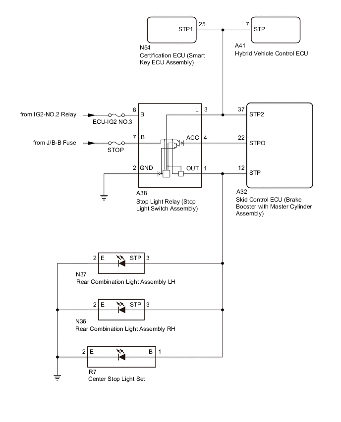
The skid control ECU (brake booster with master cylinder assembly) sends a stop light operation request signal to the stop light relay (stop light switch assembly). If the skid control ECU (brake booster with master cylinder assembly) detects a malfunction in the stop light relay circuit, the driving support ECU assembly stores DTC C1A4B.
| DTC No. | Detection Item | DTC Detection Condition | Trouble Area |
|---|---|---|---|
| C1A4B | Stop Light Relay Circuit | Both of the following conditions are met:
Tech Tips The skid control ECU (brake booster with master cylinder assembly) will detect a stop light relay circuit malfunction if any of the following conditions are met:
|
|
WIRING DIAGRAM
CAUTION / NOTICE / HINT
Note
Inspect the fuses for circuits related to this system before performing the following procedure.
PROCEDURE
-
INSPECT TERMINAL VOLTAGE (SKID CONTROL ECU (BRAKE BOOSTER WITH MASTER CYLINDER ASSEMBLY) CONNECTOR)
-
Turn the power switch off.
-
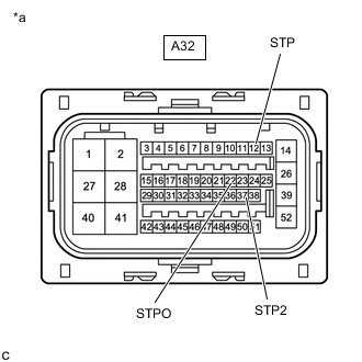
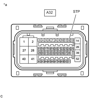
*a Front view of wire harness connector
(to Skid control ECU (Brake booster with master cylinder assembly))
Disconnect the A32 skid control ECU (brake booster with master cylinder assembly) connector.
-
Measure the voltage according to the value(s) in the table below.
Standard Voltage Tester Connection Condition Specified Condition A32-37 (STP2) - Body ground Brake pedal depressed 11 to 14 V Brake pedal released Below 1.5 V A32-22 (STPO) - Body ground Power switch ON 11 to 14 V A32-12 (STP) - Body ground Brake pedal depressed 11 to 14 V Brake pedal released Below 1.5 V -
Connect the A32 skid control ECU (brake booster with master cylinder assembly) connector.
Result Result Proceed to The voltage is as specified for every terminal. A Only the voltage at terminal STP2 is not as specified. B Only the voltage at terminal STPO is not as specified. C Only the voltage at terminal STP is not as specified. D The voltage at both terminal STPO and terminal STP are not as specified. E
B 
INSPECT TERMINAL VOLTAGE (SKID CONTROL ECU (BRAKE BOOSTER WITH MASTER CYLINDER ASSEMBLY) CONNECTOR) Click here
C
CHECK WIRE HARNESS AND CONNECTOR (SKID CONTROL ECU (BRAKE BOOSTER WITH MASTER CYLINDER ASSEMBLY) - STOP LIGHT RELAY (STOP LIGHT SWITCH ASSEMBLY)) Click here
D
INSPECT TERMINAL VOLTAGE (SKID CONTROL ECU (BRAKE BOOSTER WITH MASTER CYLINDER ASSEMBLY) CONNECTOR) Click here
E
INSPECT STOP LIGHT RELAY (STOP LIGHT SWITCH ASSEMBLY) (POWER SOURCE CIRCUIT) Click here
A 
-
-
PERFORM ACTIVE TEST USING GTS (STOP LIGHT RELAY)
-
Turn the power switch off.
-
According to the display on the GTS, perform the Active Test Stop Light Relay.
Chassis > ABS/VSC/TRC > Active TestTester Display Measurement Item Control Range Diagnostic Note Stop Light Relay Stop light relay (Stop light switch assembly) ON / OFF Test possible at vehicle speed of 0 km/h (0 mph)
Chassis > ABS/VSC/TRC > Active TestTester Display Stop Light Relay OK The stop lights turn on and off correctly in response to the operation of the Active Test. Result Proceed to OK NG
NG
INSPECT SKID CONTROL ECU (BRAKE BOOSTER WITH MASTER CYLINDER ASSEMBLY) Click here
OK
-
-
CHECK FOR DTCS (PRE-CRASH SAFETY SYSTEM)
-
Clear the DTCs.
Body Electrical > Pre-Crash 2 > Clear DTCs -
According to the display on the GTS, perform the Active Test Stop Light Relay.
Chassis > ABS/VSC/TRC > Active TestTester Display Measurement Item Control Range Diagnostic Note Stop Light Relay Stop light relay (Stop light switch assembly) ON / OFF Test possible at vehicle speed of 0 km/h (0 mph)
Chassis > ABS/VSC/TRC > Active TestTester Display Stop Light Relay -
Check for DTCs.
Body Electrical > Pre-Crash 2 > Trouble CodesOK DTC C1A4B is not output Result Proceed to OK NG
OK 
USE SIMULATION METHOD TO CHECK Click here
NG
REPLACE SKID CONTROL ECU (BRAKE BOOSTER WITH MASTER CYLINDER ASSEMBLY) for LHD: Click here for RHD: Click here
-
-
INSPECT SKID CONTROL ECU (BRAKE BOOSTER WITH MASTER CYLINDER ASSEMBLY)
-
According to the display on the GTS, perform the Active Test Stop Light Relay.
Chassis > ABS/VSC/TRC > Active TestTester Display Measurement Item Control Range Diagnostic Note Stop Light Relay Stop light relay (Stop light switch assembly) ON / OFF Test possible at vehicle speed of 0 km/h (0 mph)
Chassis > ABS/VSC/TRC > Active TestTester Display Stop Light Relay -
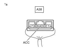
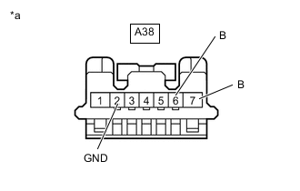
*a Component with harness connected
(Stop light relay (stop light switch assembly))
Measure the voltage according to the value(s) in the table below.
Tech Tips
Do not disconnect the stop light relay (stop light switch assembly) connector.
Standard Voltage Tester Connection Condition Specified Condition A38-4 (ACC) - Body ground Power switch on (IG)
(Active test ON)
Below 1.5 V Result Proceed to OK NG
OK
REPLACE STOP LIGHT RELAY (STOP LIGHT SWITCH ASSEMBLY) Click here
NG
REPLACE SKID CONTROL ECU (BRAKE BOOSTER WITH MASTER CYLINDER ASSEMBLY) for LHD: Click here for RHD: Click here
-
-
INSPECT TERMINAL VOLTAGE (SKID CONTROL ECU (BRAKE BOOSTER WITH MASTER CYLINDER ASSEMBLY) CONNECTOR)
-
Turn the power switch off.
-
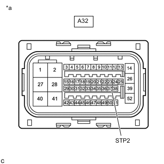
*a Front view of wire harness connector
(to Skid control ECU (Brake booster with master cylinder assembly))
Disconnect the A32 skid control ECU (brake booster with master cylinder assembly) connector.
-
Measure the voltage according to the value(s) in the table below.
Standard Voltage Tester Connection Condition Specified Condition A32-37 (STP2) - Body ground Brake pedal released Below 1.5 V -
Connect the A32 skid control ECU (brake booster with master cylinder assembly) connector.
Result Proceed to OK NG
NG
CHECK WIRE HARNESS AND CONNECTOR (SKID CONTROL ECU (BRAKE BOOSTER WITH MASTER CYLINDER ASSEMBLY) - STOP LIGHT RELAY (STOP LIGHT SWITCH ASSEMBLY)) Click here
OK
-
-
CHECK WIRE HARNESS AND CONNECTOR (SKID CONTROL ECU (BRAKE BOOSTER WITH MASTER CYLINDER ASSEMBLY) - CERTIFICATION ECU (SMART KEY ECU ASSEMBLY))
-
Turn the power switch off.
-
Disconnect the A32 skid control ECU (brake booster with master cylinder assembly) connector.
-
Disconnect the N54 certification ECU (smart key ECU assembly) connector.
-
Measure the voltage according to the value(s) in the table below.
Standard Voltage Tester Connection Condition Specified Condition A32-37 (STP2) or N54-25 (STP1) - Body ground Brake pedal depressed 11 to 14 V -
Connect the N54 certification ECU (smart key ECU assembly) connector.
-
Connect the A32 skid control ECU (brake booster with master cylinder assembly) connector.
Result Proceed to OK NG
OK
REPLACE CERTIFICATION ECU (SMART KEY ECU ASSEMBLY)
NG
-
-
CHECK WIRE HARNESS AND CONNECTOR (SKID CONTROL ECU (BRAKE BOOSTER WITH MASTER CYLINDER ASSEMBLY) - HYBRID VEHICLE CONTROL ECU)
-
Turn the power switch off.
-
Disconnect the A32 skid control ECU (brake booster with master cylinder assembly) connector.
-
Disconnect the A41 hybrid vehicle control ECU connector.
-
Measure the voltage according to the value(s) in the table below.
Standard Voltage Tester Connection Condition Specified Condition A32-37 (STP2) or A41-7 (STP) - Body ground Brake pedal depressed 11 to 14 V -
Connect the A41 hybrid vehicle control ECU connector.
-
Connect the A32 skid control ECU (brake booster with master cylinder assembly) connector.
Result Proceed to OK NG
OK
REPLACE HYBRID VEHICLE CONTROL ECU Click here
NG
-
-
CHECK WIRE HARNESS AND CONNECTOR (SKID CONTROL ECU (BRAKE BOOSTER WITH MASTER CYLINDER ASSEMBLY) - STOP LIGHT RELAY (STOP LIGHT SWITCH ASSEMBLY))
-
Turn the power switch off.
-
Disconnect the A32 skid control ECU (brake booster with master cylinder assembly) connector.
-
Disconnect the A38 stop light relay (stop light switch assembly) connector.
-
Measure the resistance according to the value(s) in the table below.
Standard Resistance Tester Connection Condition Specified Condition A32-37 (STP2) - A38-3 (L) Always Below 1 Ω A32-37 (STP2) or A38-3 (L) - Body ground Always 10 kΩ or higher -
Connect the A38 stop light relay (stop light switch assembly) connector.
-
Connect the A32 skid control ECU (brake booster with master cylinder assembly) connector.
Result Proceed to OK NG
OK
REPLACE STOP LIGHT RELAY (STOP LIGHT SWITCH ASSEMBLY) Click here
NG
REPAIR OR REPLACE HARNESS OR CONNECTOR
-
-
CHECK WIRE HARNESS AND CONNECTOR (SKID CONTROL ECU (BRAKE BOOSTER WITH MASTER CYLINDER ASSEMBLY) - STOP LIGHT RELAY (STOP LIGHT SWITCH ASSEMBLY))
-
Turn the power switch off.
-
Disconnect the A32 skid control ECU (brake booster with master cylinder assembly) connector.
-
Disconnect the A38 stop light relay (stop light switch assembly) connector.
-
Measure the voltage according to the value(s) in the table below.
Standard Voltage Tester Connection Condition Specified Condition A32-37 (STP2) or A38-3 (L) - Body ground Brake pedal released Below 1.5 V -
Connect the A38 stop light relay (stop light switch assembly) connector.
-
Connect the A32 skid control ECU (brake booster with master cylinder assembly) connector.
Result Proceed to OK NG
OK
REPLACE STOP LIGHT RELAY (STOP LIGHT SWITCH ASSEMBLY) Click here
NG
-
-
CHECK WIRE HARNESS AND CONNECTOR (SKID CONTROL ECU (BRAKE BOOSTER WITH MASTER CYLINDER ASSEMBLY) - CERTIFICATION ECU (SMART KEY ECU ASSEMBLY))
-
Turn the power switch off.
-
Disconnect the A32 skid control ECU (brake booster with master cylinder assembly) connector.
-
Disconnect the N54 certification ECU (smart key ECU assembly) connector.
-
Measure the voltage according to the value(s) in the table below.
Standard Voltage Tester Connection Condition Specified Condition A32-37 (STP2) or N54-25 (STP1) - Body ground Brake pedal released Below 1.5 V -
Connect the N54 certification ECU (smart key ECU assembly) connector.
-
Connect the A32 skid control ECU (brake booster with master cylinder assembly) connector.
Result Proceed to OK NG
OK
REPLACE CERTIFICATION ECU (SMART KEY ECU ASSEMBLY)
NG
-
-
CHECK WIRE HARNESS AND CONNECTOR (SKID CONTROL ECU (BRAKE BOOSTER WITH MASTER CYLINDER ASSEMBLY) - HYBRID VEHICLE CONTROL ECU)
-
Turn the power switch off.
-
Disconnect the A32 skid control ECU (brake booster with master cylinder assembly) connector.
-
Disconnect the A41 hybrid vehicle control ECU connector.
-
Measure the voltage according to the value(s) in the table below.
Standard Voltage Tester Connection Condition Specified Condition A32-37 (STP2) or A41-7 (STP) - Body ground Brake pedal released Below 1.5 V -
Connect the A41 hybrid vehicle control ECU connector.
-
Connect the A32 skid control ECU (brake booster with master cylinder assembly) connector.
Result Proceed to OK NG
OK
REPLACE HYBRID VEHICLE CONTROL ECU Click here
NG
REPAIR OR REPLACE HARNESS OR CONNECTOR
-
-
CHECK WIRE HARNESS AND CONNECTOR (SKID CONTROL ECU (BRAKE BOOSTER WITH MASTER CYLINDER ASSEMBLY) - STOP LIGHT RELAY (STOP LIGHT SWITCH ASSEMBLY))
-
Turn the power switch off.
-
Disconnect the A32 skid control ECU (brake booster with master cylinder assembly) connector.
-
Disconnect the A38 stop light relay (stop light switch assembly) connector.
-
Measure the resistance according to the value(s) in the table below.
Standard Resistance Tester Connection Condition Specified Condition A32-22 (STPO) - A38-4 (ACC) Always Below 1 Ω -
Connect the A38 stop light relay (stop light switch assembly) connector.
-
Connect the A32 skid control ECU (brake booster with master cylinder assembly) connector.
Result Proceed to OK NG
NG
REPAIR OR REPLACE HARNESS OR CONNECTOR
OK
-
-
INSPECT STOP LIGHT RELAY (STOP LIGHT SWITCH ASSEMBLY) (POWER SOURCE CIRCUIT)
-
Turn the power switch off.
-
*a Front view of wire harness connector
(to Stop light relay (Stop light switch assembly))
Disconnect the A38 stop light relay (stop light switch assembly) connector.
-
Measure the voltage according to the value(s) in the table below.
Standard Voltage Tester Connection Condition Specified Condition A38-6 (B) - Body ground Power switch ON 11 to 14 V A38-7 (B) - Body ground Always 11 to 14 V -
Measure the resistance according to the value(s) in the table below.
Standard Resistance Tester Connection Condition Specified Condition A38-2 (GND) - Body ground Always Below 1 Ω -
Connect the A38 stop light relay (stop light switch assembly) connector.
Result Proceed to OK NG
OK
REPLACE STOP LIGHT RELAY (STOP LIGHT SWITCH ASSEMBLY) Click here
NG
REPAIR OR REPLACE HARNESS OR CONNECTOR
-
-
INSPECT TERMINAL VOLTAGE (SKID CONTROL ECU (BRAKE BOOSTER WITH MASTER CYLINDER ASSEMBLY) CONNECTOR)
-
Turn the power switch off.
-
*a Front view of wire harness connector
(to Skid control ECU (Brake booster with master cylinder assembly))
Disconnect the A32 skid control ECU (brake booster with master cylinder assembly) connector.
-
Measure the voltage according to the value(s) in the table below.
Standard Voltage Tester Connection Condition Specified Condition A32-12 (STP) - Body ground Brake pedal released Below 1.5 V -
Connect the A32 skid control ECU (brake booster with master cylinder assembly) connector.
Result Proceed to OK NG
NG
CHECK WIRE HARNESS AND CONNECTOR (SKID CONTROL ECU (BRAKE BOOSTER WITH MASTER CYLINDER ASSEMBLY) - STOP LIGHT RELAY (STOP LIGHT SWITCH ASSEMBLY)) Click here
OK
-
-
CHECK WIRE HARNESS AND CONNECTOR (SKID CONTROL ECU (BRAKE BOOSTER WITH MASTER CYLINDER ASSEMBLY) - REAR COMBINATION LIGHT ASSEMBLY LH)
-
Turn the power switch off.
-
Disconnect the A32 skid control ECU (brake booster with master cylinder assembly) connector.
-
Disconnect the N37 rear combination light assembly LH connector.
-
Measure the voltage according to the value(s) in the table below.
Standard Voltage Tester Connection Condition Specified Condition A32-12 (STP) or N37-3 (STP) - Body ground Brake pedal depressed 11 to 14 V -
Connect the N37 rear combination light assembly LH connector.
-
Connect the A32 skid control ECU (brake booster with master cylinder assembly) connector.
Result Proceed to OK NG
OK
REPLACE REAR COMBINATION LIGHT ASSEMBLY LH Click here
NG
-
-
CHECK WIRE HARNESS AND CONNECTOR (SKID CONTROL ECU (BRAKE BOOSTER WITH MASTER CYLINDER ASSEMBLY) - REAR COMBINATION LIGHT ASSEMBLY RH)
-
Turn the power switch off.
-
Disconnect the A32 skid control ECU (brake booster with master cylinder assembly) connector.
-
Disconnect the N36 rear combination light assembly RH connector.
-
Measure the voltage according to the value(s) in the table below.
Standard Voltage Tester Connection Condition Specified Condition A32-12 (STP) or N36-3 (STP) - Body ground Brake pedal depressed 11 to 14 V -
Connect the N36 rear combination light assembly RH connector.
-
Connect the A32 skid control ECU (brake booster with master cylinder assembly) connector.
Result Proceed to OK NG
OK
REPLACE REAR COMBINATION LIGHT ASSEMBLY RH Click here
NG
-
-
CHECK WIRE HARNESS AND CONNECTOR (SKID CONTROL ECU (BRAKE BOOSTER WITH MASTER CYLINDER ASSEMBLY) - CENTER STOP LIGHT SET)
-
Turn the power switch off.
-
Disconnect the A32 skid control ECU (brake booster with master cylinder assembly) connector.
-
Disconnect the R7 center stop light set connector.
-
Measure the voltage according to the value(s) in the table below.
Standard Voltage Tester Connection Condition Specified Condition A32-12 (STP) or R7-1 (B) - Body ground Brake pedal depressed 11 to 14 V -
Connect the R7 center stop light set connector.
-
Connect the A32 skid control ECU (brake booster with master cylinder assembly) connector.
Result Proceed to OK NG
OK
REPLACE CENTER STOP LIGHT SET Click here
NG
-
-
CHECK WIRE HARNESS AND CONNECTOR (SKID CONTROL ECU (BRAKE BOOSTER WITH MASTER CYLINDER ASSEMBLY) - STOP LIGHT RELAY (STOP LIGHT SWITCH ASSEMBLY))
-
Turn the power switch off.
-
Disconnect the A32 skid control ECU (brake booster with master cylinder assembly) connector.
-
Disconnect the A38 stop light relay (stop light switch assembly) connector.
-
Measure the resistance according to the value(s) in the table below.
Standard Resistance Tester Connection Condition Specified Condition A32-12 (STP) - A38-1 (OUT) Always Below 1 Ω A32-12 (STP) or A38-1 (OUT) - Body ground Always 10 kΩ or higher -
Connect the A38 stop light relay (stop light switch assembly) connector.
-
Connect the A32 skid control ECU (brake booster with master cylinder assembly) connector.
Result Proceed to OK NG
OK
REPLACE STOP LIGHT RELAY (STOP LIGHT SWITCH ASSEMBLY) Click here
NG
REPAIR OR REPLACE HARNESS OR CONNECTOR
-
-
CHECK WIRE HARNESS AND CONNECTOR (SKID CONTROL ECU (BRAKE BOOSTER WITH MASTER CYLINDER ASSEMBLY) - STOP LIGHT RELAY (STOP LIGHT SWITCH ASSEMBLY))
-
Turn the power switch off.
-
Disconnect the A32 skid control ECU (brake booster with master cylinder assembly) connector.
-
Disconnect the A38 stop light relay (stop light switch assembly) connector.
-
Measure the voltage according to the value(s) in the table below.
Standard Voltage Tester Connection Condition Specified Condition A32-12 (STP) or A38-1 (OUT) - Body ground Brake pedal released Below 1.5 V -
Connect the A38 stop light relay (stop light switch assembly) connector.
-
Connect the A32 skid control ECU (brake booster with master cylinder assembly) connector.
Result Proceed to OK NG
OK
REPLACE STOP LIGHT RELAY (STOP LIGHT SWITCH ASSEMBLY) Click here
NG
-
-
CHECK WIRE HARNESS AND CONNECTOR (SKID CONTROL ECU (BRAKE BOOSTER WITH MASTER CYLINDER ASSEMBLY) - REAR COMBINATION LIGHT ASSEMBLY LH)
-
Turn the power switch off.
-
Disconnect the A32 skid control ECU (brake booster with master cylinder assembly) connector.
-
Disconnect the N37 rear combination light assembly LH connector.
-
Measure the voltage according to the value(s) in the table below.
Standard Voltage Tester Connection Condition Specified Condition A32-12 (STP) or N37-3 (STP) - Body ground Brake pedal released Below 1.5 V -
Connect the N37 rear combination light assembly LH connector.
-
Connect the A32 skid control ECU (brake booster with master cylinder assembly) connector.
Result Proceed to OK NG
OK
REPLACE REAR COMBINATION LIGHT ASSEMBLY LH Click here
NG
-
-
CHECK WIRE HARNESS AND CONNECTOR (SKID CONTROL ECU (BRAKE BOOSTER WITH MASTER CYLINDER ASSEMBLY) - REAR COMBINATION LIGHT ASSEMBLY RH)
-
Turn the power switch off.
-
Disconnect the A32 skid control ECU (brake booster with master cylinder assembly) connector.
-
Disconnect the N36 rear combination light assembly RH connector.
-
Measure the voltage according to the value(s) in the table below.
Standard Voltage Tester Connection Condition Specified Condition A32-12 (STP) or N36-3 (STP) - Body ground Brake pedal released Below 1.5 V -
Connect the N36 rear combination light assembly RH connector.
-
Connect the A32 skid control ECU (brake booster with master cylinder assembly) connector.
Result Proceed to OK NG
OK
REPLACE REAR COMBINATION LIGHT ASSEMBLY RH Click here
NG
-
-
CHECK WIRE HARNESS AND CONNECTOR (SKID CONTROL ECU (BRAKE BOOSTER WITH MASTER CYLINDER ASSEMBLY) - CENTER STOP LIGHT SET)
-
Turn the power switch off.
-
Disconnect the A32 skid control ECU (brake booster with master cylinder assembly) connector.
-
Disconnect the R7 center stop light set connector.
-
Measure the voltage according to the value(s) in the table below.
Standard Voltage Tester Connection Condition Specified Condition A32-12 (STP) or R7-1 (B) - Body ground Brake pedal released Below 1.5 V -
Connect the R7 center stop light set connector.
-
Connect the A32 skid control ECU (brake booster with master cylinder assembly) connector.
Result Proceed to OK NG
OK
REPLACE CENTER STOP LIGHT SET Click here
NG
REPAIR OR REPLACE HARNESS OR CONNECTOR
-
-
INSPECT STOP LIGHT RELAY (STOP LIGHT SWITCH ASSEMBLY) (POWER SOURCE CIRCUIT)
-
Turn the power switch off.
-
*a Front view of wire harness connector
(to Stop light relay (Stop light switch assembly))
Disconnect the A38 stop light relay (stop light switch assembly) connector.
-
Measure the voltage according to the value(s) in the table below.
Standard Voltage Tester Connection Condition Specified Condition A38-6 (B) - Body ground Power switch ON 11 to 14 V A38-7 (B) - Body ground Always 11 to 14 V -
Measure the resistance according to the value(s) in the table below.
Standard Resistance Tester Connection Condition Specified Condition A38-2 (GND) - Body ground Always Below 1 Ω -
Connect the A38 stop light relay (stop light switch assembly) connector.
Result Proceed to OK NG
NG
REPAIR OR REPLACE HARNESS OR CONNECTOR
OK
-
-
CHECK WIRE HARNESS AND CONNECTOR (SKID CONTROL ECU (BRAKE BOOSTER WITH MASTER CYLINDER ASSEMBLY) - STOP LIGHT RELAY (STOP LIGHT SWITCH ASSEMBLY))
-
Turn the power switch off.
-
Disconnect the A32 skid control ECU (brake booster with master cylinder assembly) connector.
-
Disconnect the A38 stop light relay (stop light switch assembly) connector.
-
Measure the resistance according to the value(s) in the table below.
Standard Resistance Tester Connection Condition Specified Condition A32-22 (STPO) or A38-4 (ACC) - Body ground Always 10 kΩ or higher -
Connect the A38 stop light relay (stop light switch assembly) connector.
-
Connect the A32 skid control ECU (brake booster with master cylinder assembly) connector.
Result Proceed to OK NG
OK
REPLACE STOP LIGHT RELAY (STOP LIGHT SWITCH ASSEMBLY) Click here
NG
REPAIR OR REPLACE HARNESS OR CONNECTOR
-