SPIRAL CABLE REMOVAL
CAUTION / NOTICE / HINT
The necessary procedures (adjustment, calibration, initialization, or registration) that must be performed after parts are removed, installed, or replaced during the spiral cable sub-assembly removal/installation are shown below.
| Replacement Part or Procedure | Necessary Procedures | Effects / Inoperative when not performed | Link |
|---|---|---|---|
| Disconnect cable from negative auxiliary battery terminal | Memorize steering angle neutral point | Lane departure alert system (w/ Steering Control) | |
| Intelligent clearance sonar system*1 | |||
| Simple intelligent parking assist system*1 | |||
| Pre-crash safety system | |||
| Adaptive high beam system | |||
| Parking assist monitor system | |||
| Initialize back door lock | Power door lock control system | ||
| Removal/installation of the spiral cable with sensor sub-assembly | Steering angle neutral point (Initialize intelligent clearance sonar system) |
|
|
| Steering angle setting | Parking assist monitor system |
Click here Click here
PROCEDURE
-
REMOVE STEERING WHEEL ASSEMBLY
-
ALIGN FRONT WHEELS FACING STRAIGHT AHEAD
-
INSPECT SPIRAL CABLE WITH SENSOR SUB-ASSEMBLY
-
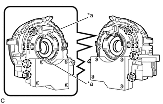
Check the flat cable shown in the illustration.
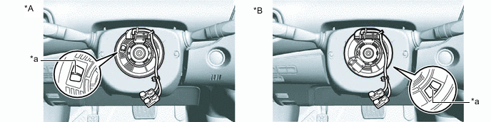
*A w/o Steering Heater *B w/ Steering Heater *a Flat Cable - - If the flat cable shown in the illustration is not visible, it is possible that the spiral cable with sensor sub-assembly is broken. Replace the spiral cable with sensor sub-assembly with a new one.
-
-
REMOVE LOWER STEERING COLUMN COVER SUB-ASSEMBLY
-
REMOVE UPPER STEERING COLUMN COVER
-
REMOVE SPIRAL CABLE WITH SENSOR SUB-ASSEMBLY
Note
-
Do not replace the spiral cable with sensor sub-assembly with the auxiliary battery connected and the power switch on (IG).
-
Do not rotate the spiral cable with sensor sub-assembly without the steering wheel assembly installed, with the auxiliary battery connected and the power switch on (IG).
-
Ensure that the steering wheel assembly is installed and aligned straight when inspecting the steering sensor.
-
Check that the power switch is off.
-
Check that the cable is disconnected from the negative (-) auxiliary battery terminal.
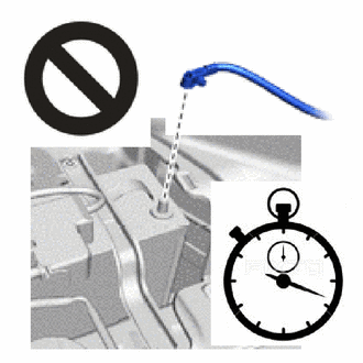
CAUTION:
Wait at least 90 seconds after disconnecting the cable from the negative (-) auxiliary battery terminal to disable the SRS system.
-
Check that the front wheels are aligned facing straight ahead.
-
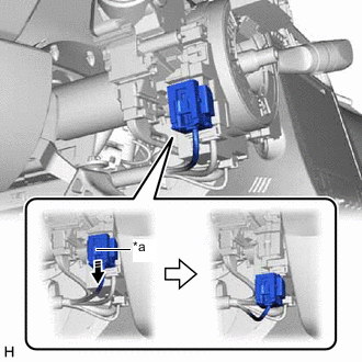
*a Slider Slide the slider to release the lock, and then disconnect the yellow airbag connector from the spiral cable with sensor sub-assembly.
Note
When disconnecting any airbag connector, take care not to damage the airbag wire harness.
-
Disconnect the other connectors from the spiral cable with sensor sub-assembly.
-
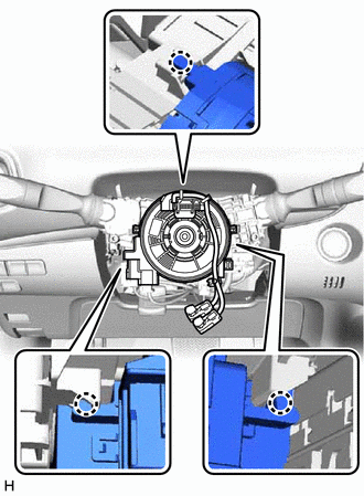
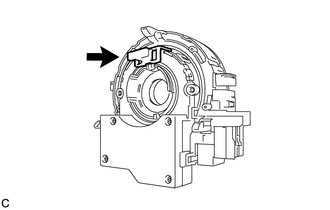
Disengage the 3 claws to remove the spiral cable with sensor sub-assembly.
-
-
REMOVE SPIRAL CABLE SUB-ASSEMBLY
Note
-
Remove the steering sensor from the spiral cable sub-assembly only when replacing the spiral cable sub-assembly or the steering sensor.
-
Removing the steering sensor from the spiral cable sub-assembly without using a lock pin may result in the center position of the steering sensor becoming misaligned. Therefore, make sure to use the lock pin provided with a new spiral cable sub-assembly when removing the steering sensor from the spiral cable sub-assembly.
-
When replacing the steering sensor:
-
Install the lock pin to the steering sensor.
Note
-
Use the lock pin provided with a new spiral cable sub-assembly.
-
Do not remove the lock pin before installing the steering sensor to the spiral cable sub-assembly.
-
-
*a Guide Disengage the 6 claws and 2 pins, and remove the spiral cable sub-assembly from the steering sensor.
Note
Do not damage the pins of the spiral cable sub-assembly or guides of the steering sensor.
-