HEADUP DISPLAY DISASSEMBLY
PROCEDURE
-
REMOVE NO. 1 COMBINATION METER MIRROR CASE
-
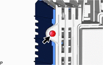
Remove the screw.
-
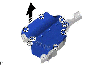

Remove in this Direction Disengage the 6 claws and 2 guides to remove the No. 1 combination meter mirror case as shown in the illustration.
-
-
REMOVE NO. 1 COMBINATION METER MIRROR PLATE
-
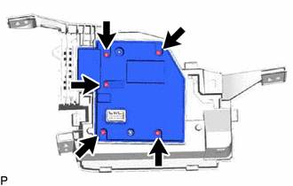
Remove the 5 screws and No. 1 combination meter mirror plate.
-
-
REMOVE COMBINATION METER MIRROR ECU
-
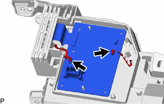
Disconnect the 2 connectors.
-
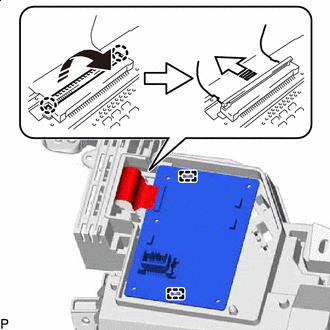
Remove in this Direction (1) 
Remove in this Direction (2) Disengage the 2 claws and raise the holder in the direction indicated by the arrow (1) shown in the illustration.
Note
Make sure not to rotate the holder 90° or more, or it may be damaged.
-
Disconnect the connector in the direction indicated by the arrow (2) shown in the illustration.
-
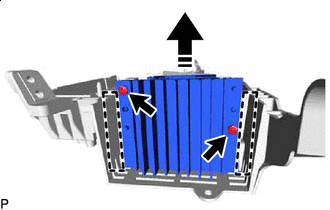
Disengage the 2 guides to remove the combination meter mirror ECU.
-
-
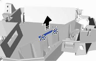
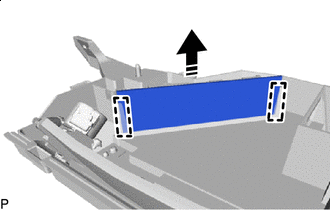
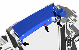
REMOVE COMBINATION DISPLAY
-
Remove in this Direction Remove the 2 screws.
-
Disengage the 2 guides to remove the combination display as shown in the illustration.
-
-
REMOVE COMBINATION METER WIRE
-
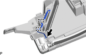
Disconnect the connector.
-
Disengage the 2 clamps to remove the combination meter wire.
-
-
REMOVE COMBINATION METER MIRROR
-
Remove in this Direction Disengage the 2 claws and remove the mirror clip as shown in the illustration.
-
Remove in this Direction Disengage the 2 guides to remove the combination meter mirror as shown in the illustration.
-
-
REMOVE NO. 2 COMBINATION METER MIRROR
-
Remove the 3 screws.
-
Disengage the 2 guides to remove the No. 2 combination meter mirror.
-