COMBINATION METER DISASSEMBLY
PROCEDURE
-
REMOVE COMBINATION METER GLASS
-
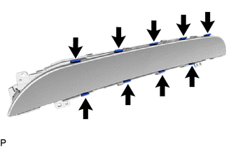
Remove the 9 bushes.
-
Disengage the 12 claws to remove the combination meter glass.
-
-
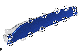
REMOVE NO. 1 COMBINATION METER COVER
-
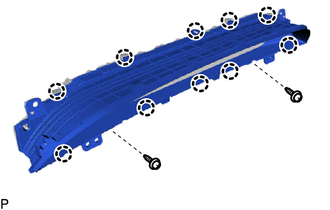
Remove the 2 screws.
-
Disengage the 10 claws to remove the No. 1 combination meter cover.
-
-
REMOVE NO. 1 COMBINATION METER PLATE
-
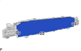
Disengage the 3 guides and remove the No. 1 combination meter plate.
-
-
REMOVE NO. 2 COMBINATION METER CASE
-
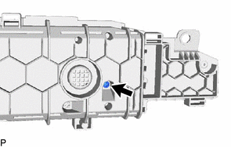
Remove the screw.
-
Disengage the 2 guides and remove the No. 2 combination meter case.
-
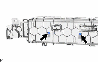
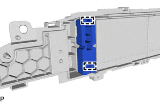
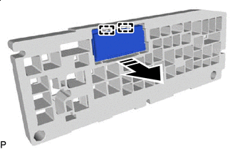
Remove the 2 screws.
-

Remove in this Direction Disengage the 2 guides and disconnect the connector to remove the No. 2 combination meter case with combination meter multi-display as shown in the illustration.
Note
-
Make sure to pull the connector straight up when disconnecting it as it is easily damaged.
-
Do not apply excessive force to the connector.
-
-
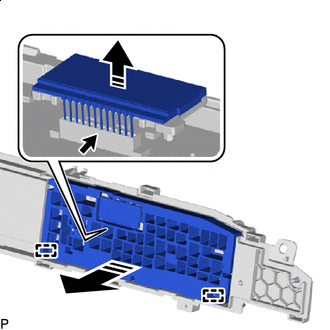
Remove in this Direction Disengage the 2 guides to remove the combination meter multi-display from the No. 2 combination meter case as shown in the illustration.
-
-
REMOVE NO. 2 METER CIRCUIT PLATE
-
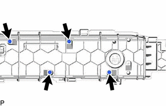
Remove the 4 screws.
-
Remove in this Direction Disengage the 4 guides to remove the No. 2 meter circuit plate as shown in the illustration.
-
-
REMOVE METER CIRCUIT PLATE
-
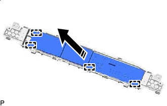
Remove in this Direction Disengage the 4 claws and 4 guides as shown in the illustration.
-
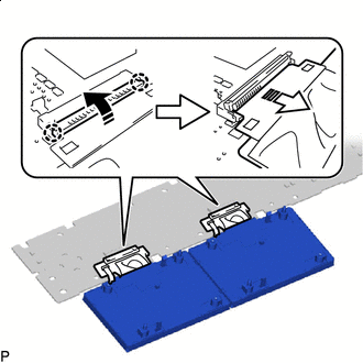
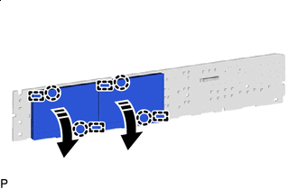
Remove in this Direction (1) 
Remove in this Direction (2) Disengage the 4 claws and raise each holder in the direction indicated by the arrow (1) shown in the illustration.
Note
Make sure not to rotate the holder 90° or more, or it may be damaged.
-
Disconnect each connector in the direction indicated by the arrow (2) shown in the illustration to remove the TFT display from the meter circuit plate.
-