COMBINATION METER REMOVAL
CAUTION / NOTICE / HINT
The necessary procedures (adjustment, calibration, initialization or registration) that must be performed after parts are removed and installed, or replaced during combination meter assembly removal/installation are shown below.
| Replaced Part or Performed Procedure | Necessary Procedure | Effect/Inoperative Function when Necessary Procedure not Performed | Link |
|---|---|---|---|
| Disconnect cable from negative (-) auxiliary battery terminal | Memorize steering angle neutral point | Lane departure alert system (w/ Steering Control) | |
| Intelligent clearance sonar system*1 | |||
| Simple intelligent parking assist system*1 | |||
| Pre-crash safety system | |||
| Adaptive high beam system | |||
| Parking assist monitor system | |||
| Initialize back door lock | Power door lock control system |
*1: When performing learning using the GTS.
PROCEDURE
-
PRECAUTION
Note
After turning the power switch off, waiting time may be required before disconnecting the cable from the negative (-) auxiliary battery terminal. Therefore, make sure to read the disconnecting the cable from the negative (-) auxiliary battery terminal notices before proceeding with work.
-
DISCONNECT CABLE FROM NEGATIVE AUXILIARY BATTERY TERMINAL
-
DISCONNECT FRONT DOOR OPENING TRIM WEATHERSTRIP LH
-
REMOVE FRONT PILLAR GARNISH LH
-
REMOVE NO. 1 INSTRUMENT PANEL SPEAKER PANEL SUB-ASSEMBLY
-
DISCONNECT FRONT DOOR OPENING TRIM WEATHERSTRIP RH
-
REMOVE FRONT PILLAR GARNISH RH
Tech Tips
Use the same procedure as for the LH side.
-
REMOVE NO. 2 INSTRUMENT PANEL SPEAKER PANEL SUB-ASSEMBLY
-
REMOVE INSTRUMENT CLUSTER FINISH PANEL ASSEMBLY
-
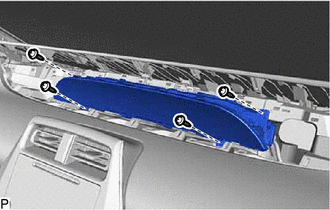
Apply protective tape to the areas shown in the illustration.
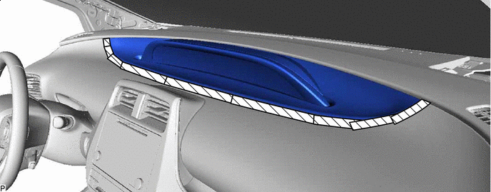

Protective Tape - - -
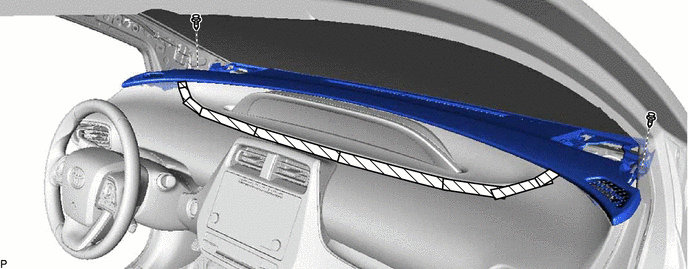
Remove the 2 clips.
-
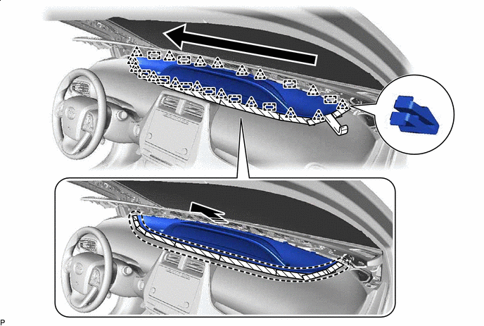
Disengage the 11 clips and 4 guides as shown in the illustration.
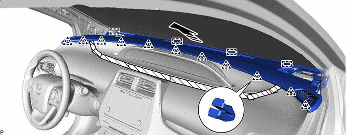

Remove in this Direction - - Note
-
Do not damage the upper instrument panel assembly.
-
Do not allow the wire harnesses to interfere with the surrounding parts.
-
-
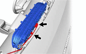
Lift the upper instrument panel assembly as shown in the illustration.
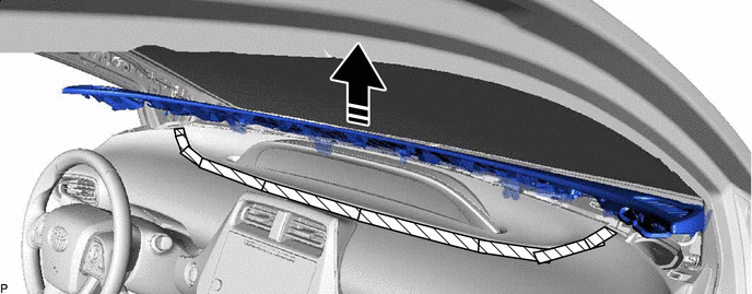
Lift in this Direction - - Note
-
Do not damage the upper instrument panel assembly.
-
Do not allow the wire harnesses to interfere with the surrounding parts.
-
-
Using a moulding remover, slightly lift the instrument cluster finish panel assembly and then disengage the 17 clips and 10 guides as shown in the illustration to remove the instrument cluster finish panel assembly.

Insert Moulding Remover Here Remove in this Direction 
Order of Removal - -
-
-
REMOVE COMBINATION METER ASSEMBLY
-
Remove the 4 screws.
-
Disengage the clamp.
-
Disconnect the 2 connectors to remove the combination meter assembly.
-