METER / GAUGE SYSTEM Speedometer Malfunction
DESCRIPTION
The combination meter assembly (meter circuit plate) receives vehicle speed signals from the skid control ECU (brake booster with master cylinder assembly) via CAN communication. The speed sensor detects the wheel speed and sends the appropriate signals to the skid control ECU (brake booster with master cylinder assembly). The skid control ECU (brake booster with master cylinder assembly) supplies power to the vehicle speed sensor. The skid control ECU (brake booster with master cylinder assembly) detects vehicle speed signals based on pulses of the voltage.
Tech Tips
Factors that affect the indicated vehicle speed include the tire size, tire inflation, and tire wear. The speed indicated on the speedometer has an allowable margin of error.
WIRING DIAGRAM
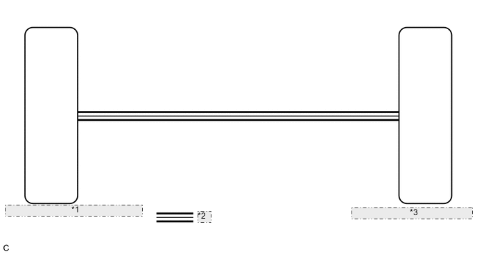
| *1 | Skid Control ECU (Brake Booster with Master Cylinder Assembly) |
| *2 | CAN Communication Line |
| *3 | Combination Meter Assembly (Meter Circuit Plate) |
CAUTION / NOTICE / HINT
Note
-
When replacing the combination meter assembly, always replace it with a new one. If a combination meter assembly which was installed to another vehicle is used, the information stored in it will not match the information from the vehicle and a DTC may be stored.
-
Before starting the following inspection, inspect the speedometer and that the tire size and air pressure are as specified.
Tire size and air pressure: Click here
Speedometer: Click here
PROCEDURE
-
CHECK CAN COMMUNICATION SYSTEM
-
Check if CAN communication DTCs are output.
Result Result Proceed to DTCs are not output A DTCs are output B
B 
GO TO CAN COMMUNICATION SYSTEM Click here
A 
-
-
CHECK FOR DTC (ELECTRONICALLY CONTROLLED BRAKE SYSTEM)
-
Check if electronically controlled brake system DTCs are output.
Chassis > ABS/VSC/TRC > Trouble CodesResult Result Proceed to DTCs are not output A DTCs are output B
B
GO TO ELECTRONICALLY CONTROLLED BRAKE SYSTEM Click here
A
-
-
PERFORM ACTIVE TEST USING GTS (SPEED METER OPERATION)
-
Connect the GTS to the DLC3.
-
Turn the power switch on (IG).
-
Turn the GTS on.
-
Enter the following menus: Body Electrical / Combination Meter / Active Test.
-
Perform the Active Test according to the display on the GTS.
Body Electrical > Combination Meter > Active TestTester Display Measurement Item Control Range Diagnostic Note Speed Meter Operation Speedometer OFF, 0, 40, 80, 120 or 160 There is a deviation in the values displayed on the speedometer (Control range → Speedometer display)
-
40 → 42 to 44
-
80 → 83 to 85
-
120 → 125 to 127
-
160 → 166 to 168
Reference mph:
-
40 → 42 to 44
-
80 → 84 to 86
-
120 → 125 to 127
-
160 → 167 to 169
Reference km/h:
Body Electrical > Combination Meter > Active TestTester Display Speed Meter Operation OK Speedometer indication is normal. Result Proceed to OK NG -
OK
REPLACE SKID CONTROL ECU (BRAKE BOOSTER WITH MASTER CYLINDER ASSEMBLY) for LHD: Click here
REPLACE SKID CONTROL ECU (BRAKE BOOSTER WITH MASTER CYLINDER ASSEMBLY) for RHD: Click hereNG
REPLACE COMBINATION METER ASSEMBLY (METER CIRCUIT PLATE) Click here
-