METER / GAUGE SYSTEM, Diagnostic DTC:B1508
| DTC Code | DTC Name |
|---|---|
| B1508 | Short in Turn Signal / Hazard Flasher Circuit |
DESCRIPTION
This DTC is stored when the combination meter assembly (meter circuit plate) detects an short in a turn signal light circuit.
Tech Tips
If there is a short in a turn signal light circuit, all of the turn signal lights on the side with the short circuit will not blink.
| DTC No. | Detection Item | DTC Detection Condition | Trouble Area | Memory | Note |
|---|---|---|---|---|---|
| B1508 | Short in Turn Signal / Hazard Flasher Circuit | Diagnosis Condition:
Malfunction Status:
|
|
DTC stored | - |
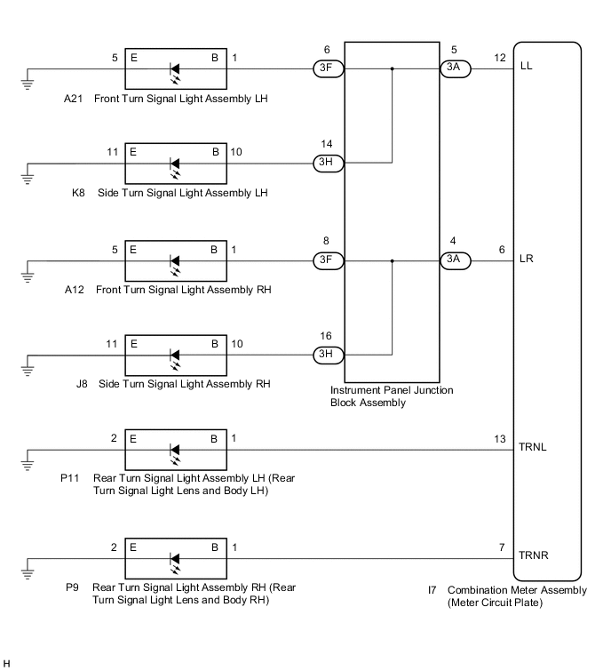
WIRING DIAGRAM
CAUTION / NOTICE / HINT
Note
-
When replacing the combination meter assembly, always replace it with a new one. If a combination meter assembly which was installed to another vehicle is used, the information stored in it will not match the information from the vehicle and a DTC may be stored.
-
Inspect the turn signal lights for this system before performing the following procedure.
Rear turn signal light assembly: Click here
Side turn signal light assembly: Click here
Front turn signal light assembly: Click here
PROCEDURE
-
INSPECT LIGHTS
-
Inspect the illumination of each turn signal light.
Result Result Proceed to All LH turn signal lights do not blink A All RH turn signal lights do not blink B
B 
CHECK HARNESS AND CONNECTOR (REAR TURN SIGNAL LIGHT ASSEMBLY RH - COMBINATION METER ASSEMBLY (METER CIRCUIT PLATE)) Click here
A 
-
-
CHECK HARNESS AND CONNECTOR (REAR TURN SIGNAL LIGHT ASSEMBLY LH - COMBINATION METER ASSEMBLY (METER CIRCUIT PLATE))
-
Disconnect the P11 rear turn signal light assembly LH (rear turn signal light lens and body LH) connector.
-
Disconnect the I7 combination meter assembly (meter circuit plate) connector.
-
Measure the resistance according to the value(s) in the table below.
Standard Resistance Tester Connection Condition Specified Condition P11-1 (B) or I7-13 (TRNL) - Body ground Always 10 kΩ or higher Result Proceed to OK NG
NG 
REPAIR OR REPLACE HARNESS OR CONNECTOR
OK
-
-
CHECK HARNESS AND CONNECTOR (INSTRUMENT PANEL JUNCTION BLOCK ASSEMBLY - COMBINATION METER ASSEMBLY (METER CIRCUIT PLATE))
-
Disconnect the 3A instrument panel junction block assembly connector.
-
Measure the resistance according to the value(s) in the table below.
Standard Resistance Tester Connection Condition Specified Condition 3A-5 or I7-12 (LL) - Body ground Always 10 kΩ or higher Result Proceed to OK NG
NG
REPAIR OR REPLACE HARNESS OR CONNECTOR
OK
-
-
CHECK HARNESS AND CONNECTOR (FRONT TURN SIGNAL LIGHT ASSEMBLY LH - INSTRUMENT PANEL JUNCTION BLOCK ASSEMBLY)
-
Disconnect the A21 front turn signal light assembly LH connector.
-
Disconnect the 3F instrument panel junction block assembly connector.
-
Measure the resistance according to the value(s) in the table below.
Standard Resistance Tester Connection Condition Specified Condition A21-1 (B) or 3F-6 - Body ground Always 10 kΩ or higher Result Proceed to OK NG
NG
REPAIR OR REPLACE HARNESS OR CONNECTOR
OK
-
-
CHECK HARNESS AND CONNECTOR (SIDE TURN SIGNAL LIGHT ASSEMBLY LH - INSTRUMENT PANEL JUNCTION BLOCK ASSEMBLY)
-
Disconnect the K8 side turn signal light assembly LH connector.
-
Disconnect the 3H instrument panel junction block assembly connector.
-
Measure the resistance according to the value(s) in the table below.
Standard Resistance Tester Connection Condition Specified Condition K8-10 (B) or 3H-14 - Body ground Always 10 kΩ or higher Result Proceed to OK NG
NG
REPAIR OR REPLACE HARNESS OR CONNECTOR
OK
-
-
INSPECT INSTRUMENT PANEL JUNCTION BLOCK ASSEMBLY
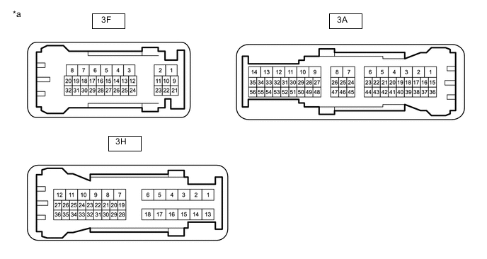
*a Component without harness connected
(Instrument Panel Junction Block Assembly)
- -
-
Measure the resistance according to the value(s) in the table below.
Note
Make sure to perform this step with the instrument panel junction block assembly installed to the vehicle.
Standard Resistance Tester Connection Condition Specified Condition 3F-6, 3H-14 or 3A-5 - Body ground Always 10 kΩ or higher Result Proceed to OK NG
OK
REPLACE COMBINATION METER ASSEMBLY (METER CIRCUIT PLATE) Click here
NG
REPLACE INSTRUMENT PANEL JUNCTION BLOCK ASSEMBLY Click here
-
-
CHECK HARNESS AND CONNECTOR (REAR TURN SIGNAL LIGHT ASSEMBLY RH - COMBINATION METER ASSEMBLY (METER CIRCUIT PLATE))
-
Disconnect the P9 rear turn signal light assembly RH (rear turn signal light lens and body RH) connector.
-
Disconnect the I7 combination meter assembly (meter circuit plate) connector.
-
Measure the resistance according to the value(s) in the table below.
Standard Resistance Tester Connection Condition Specified Condition P9-1 (B) or I7-7 (TRNR) - Body ground Always 10 kΩ or higher Result Proceed to OK NG
NG
REPAIR OR REPLACE HARNESS OR CONNECTOR
OK
-
-
CHECK HARNESS AND CONNECTOR (INSTRUMENT PANEL JUNCTION BLOCK ASSEMBLY - COMBINATION METER ASSEMBLY (METER CIRCUIT PLATE))
-
Disconnect the 3A instrument panel junction block assembly connector.
-
Measure the resistance according to the value(s) in the table below.
Standard Resistance Tester Connection Condition Specified Condition 3A-4 or I7-6 (LR) - Body ground Always 10 kΩ or higher Result Proceed to OK NG
NG
REPAIR OR REPLACE HARNESS OR CONNECTOR
OK
-
-
CHECK HARNESS AND CONNECTOR (FRONT TURN SIGNAL LIGHT ASSEMBLY RH - INSTRUMENT PANEL JUNCTION BLOCK ASSEMBLY)
-
Disconnect the A12 front turn signal light assembly RH connector.
-
Disconnect the 3F instrument panel junction block assembly connector.
-
Measure the resistance according to the value(s) in the table below.
Standard Resistance Tester Connection Condition Specified Condition A12-1 (B) or 3F-8 - Body ground Always 10 kΩ or higher Result Proceed to OK NG
NG
REPAIR OR REPLACE HARNESS OR CONNECTOR
OK
-
-
CHECK HARNESS AND CONNECTOR (SIDE TURN SIGNAL LIGHT ASSEMBLY RH - INSTRUMENT PANEL JUNCTION BLOCK ASSEMBLY)
-
Disconnect the J8 side turn signal light assembly RH connector.
-
Disconnect the 3H instrument panel junction block assembly connector.
-
Measure the resistance according to the value(s) in the table below.
Standard Resistance Tester Connection Condition Specified Condition J8-10 (B) or 3H-16 - Body ground Always 10 kΩ or higher Result Proceed to OK NG
NG
REPAIR OR REPLACE HARNESS OR CONNECTOR
OK
-
-
INSPECT INSTRUMENT PANEL JUNCTION BLOCK ASSEMBLY
*a Component without harness connected
(Instrument Panel Junction Block Assembly)
- -
-
Measure the resistance according to the value(s) in the table below.
Note
Make sure to perform this step with the instrument panel junction block assembly installed to the vehicle.
Standard Resistance Tester Connection Condition Specified Condition 3F-8, 3H-16 or 3A-4 - Body ground Always 10 kΩ or higher Result Proceed to OK NG
OK
REPLACE COMBINATION METER ASSEMBLY (METER CIRCUIT PLATE) Click here
NG
REPLACE INSTRUMENT PANEL JUNCTION BLOCK ASSEMBLY Click here
-