METER / GAUGE SYSTEM, Diagnostic DTC:B1500
| DTC Code | DTC Name |
|---|---|
| B1500 | Fuel Sender Open Detected |
DESCRIPTION
This DTC is stored when the combination meter assembly (meter circuit plate) detects a fuel sender gauge assembly malfunction via a direct line.
| DTC No. | Detection Item | DTC Detection Condition | Trouble Area | Memory | Note |
|---|---|---|---|---|---|
| B1500 | Fuel Sender Open Detected | Diagnosis Condition:
Malfunction Status:
|
|
- | - |
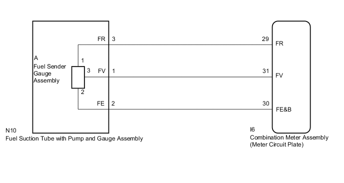
WIRING DIAGRAM
CAUTION / NOTICE / HINT
Note
When replacing the combination meter assembly, always replace it with a new one. If a combination meter assembly which was installed to another vehicle is used, the information stored in it will not match the information from the vehicle and a DTC may be stored.
PROCEDURE
-
READ VALUE USING GTS (FUEL INPUT)
-
Connect the GTS to the DLC3.
-
Turn the power switch on (IG).
-
Turn the GTS on.
-
Enter the following menus: Body Electrical / Combination Meter / Data List.
-
Read the Data List according to the display on the GTS.
Body Electrical > Combination Meter > Data ListTester Display Measurement Item Range Normal Condition Diagnostic Note Fuel Input Fuel input Min.: 0 L, Max.: 127.5 L
-
Fuel receiver gauge indicates F: 38.3 L
-
Fuel receiver gauge indicates 3/4: 29.8 L
-
Fuel receiver gauge indicates 1/2: 21.3 L
-
Fuel receiver gauge indicates 1/4: 12.8 L
-
Fuel receiver gauge indicates E: 4.3 L
w/ Canister Pump Module:
-
Fuel receiver gauge indicates F (1/1): 38.3 L
-
Fuel receiver gauge indicates 3/4: 29.9 L
-
Fuel receiver gauge indicates 1/2: 21.4 L
-
Fuel receiver gauge indicates 1/4: 12.8 L
-
Fuel receiver gauge indicates E (R): 4.3 L
w/o Canister Pump Module:
-
Body Electrical > Combination Meter > Data ListTester Display Fuel Input Result Result Proceed to Fuel level data can be displayed on the GTS A Fuel level data cannot be displayed on the GTS B -
A 
REPLACE COMBINATION METER ASSEMBLY (METER CIRCUIT PLATE) Click here
B 
-
-
INSPECT FUEL SENDER GAUGE ASSEMBLY (POWER SOURCE)
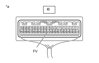
*a Component with harness connected
(Combination Meter Assembly (Meter Circuit Plate))
-
Measure the voltage according to the value(s) in the table below.
Standard Voltage Tester Connection Condition Specified Condition I6-31 (FV) - Body ground Power switch on (IG) 4.5 to 5.5 V Result Proceed to OK NG
NG
REPLACE COMBINATION METER ASSEMBLY (METER CIRCUIT PLATE) Click here
OK
-
-
INSPECT FUEL SENDER GAUGE ASSEMBLY
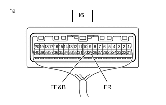
*a Component with harness connected
(Combination Meter Assembly (Meter Circuit Plate))
-
Measure the voltage according to the value(s) in the table below.
Standard Voltage Tester Connection Condition Specified Condition I6-29 (FR) - I6-30 (FE&B) Power switch on (IG) 0.2 to 4.7 V Result Proceed to OK NG
OK
REPLACE COMBINATION METER ASSEMBLY (METER CIRCUIT PLATE) Click here
NG
-
-
CHECK HARNESS AND CONNECTOR (FUEL SUCTION TUBE WITH PUMP AND GAUGE ASSEMBLY - COMBINATION METER ASSEMBLY (METER CIRCUIT PLATE))
-
Disconnect the N10 fuel suction tube with pump and gauge assembly connector.
-
Disconnect the I6 combination meter assembly (meter circuit plate) connector.
-
Measure the resistance according to the value(s) in the table below.
Standard Resistance Tester Connection Condition Specified Condition N10-3 (FR) - I6-29 (FR) Always Below 1 Ω N10-2 (FE) - I6-30 (FE&B) Always Below 1 Ω N10-1 (FV) - I6-31 (FV) Always Below 1 Ω N10-3 (FR) or I6-29 (FR) - Body ground Always 10 kΩ or higher N10-2 (FE) or I6-30 (FE&B) - Body ground Always 10 kΩ or higher N10-1 (FV) or I6-31 (FV) - Body ground Always 10 kΩ or higher Result Proceed to OK NG
NG
REPAIR OR REPLACE HARNESS OR CONNECTOR
OK
-
-
INSPECT FUEL SENDER GAUGE ASSEMBLY
-
Remove the fuel sender gauge assembly.
w/ Canister Pump Module: Click here
w/o Canister Pump Module: Click here
-
Inspect the fuel sender gauge assembly.
w/ Canister Pump Module: Click here
w/o Canister Pump Module: Click here
Result Proceed to OK NG
NG
REPLACE FUEL SENDER GAUGE ASSEMBLY w/ Canister Pump Module: Click here
REPLACE FUEL SENDER GAUGE ASSEMBLY w/o Canister Pump Module: Click hereOK
-
-
INSPECT FUEL SUCTION TUBE WITH PUMP AND GAUGE ASSEMBLY
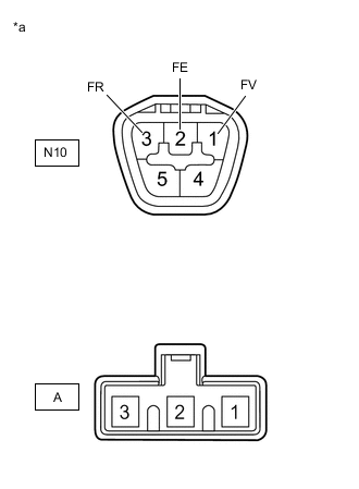
*a Component without harness connected
(Fuel Suction Tube with Pump and Gauge Assembly)
-
Measure the resistance according to the value(s) in the table below.
Standard Resistance Tester Connection Condition Specified Condition N10-1 - A-3 Always Below 1 Ω N10-2 - A-2 Always Below 1 Ω N10-3 - A-1 Always Below 1 Ω Result Proceed to OK NG
OK
REPLACE COMBINATION METER ASSEMBLY (METER CIRCUIT PLATE) Click here
NG
REPLACE FUEL SUCTION TUBE WITH PUMP AND GAUGE ASSEMBLY w/ Canister Pump Module: Click here
REPLACE FUEL SUCTION TUBE WITH PUMP AND GAUGE ASSEMBLY w/o Canister Pump Module: Click here -