LIGHTING SYSTEM Footwell Light Circuit
DESCRIPTION
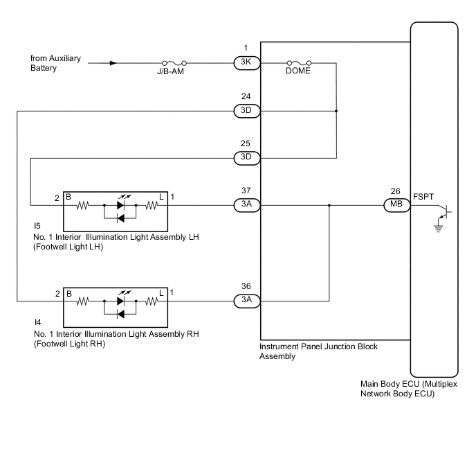
The main body ECU (multiplex network body ECU) controls the footwell lights.
WIRING DIAGRAM
CAUTION / NOTICE / HINT
Note
-
Inspect the fuses for circuits related to this system before performing the following procedure.
-
Before replacing the main body ECU (multiplex network body ECU), refer to Service Bulletin.
PROCEDURE
-
PERFORM ACTIVE TEST USING GTS
-
Connect the GTS to the DLC3.
-
Turn the power switch on (IG).
-
Turn the GTS on.
-
Enter the following menus: Body Electrical / Main Body / Active Test.
-
Perform the Active Test according to the display on the GTS.
Body Electrical > Main Body > Active TestTester Display Measurement Item Control Range Diagnostic Note Fr Foot Light Footwell light OFF or ON -
Body Electrical > Main Body > Active TestTester Display Fr Foot Light OK Footwell lights come on. Result Proceed to OK NG
OK 
PROCEED TO NEXT SUSPECTED AREA SHOWN IN PROBLEM SYMPTOMS TABLE Click here
NG 
-
-
CHECK HARNESS AND CONNECTOR (AUXILIARY BATTERY - INSTRUMENT PANEL JUNCTION BLOCK ASSEMBLY)
-
Disconnect the 3K instrument panel junction block assembly connector.
-
Measure the voltage according to the value(s) in the table below.
Standard Voltage Tester Connection Condition Specified Condition 3K-1 - Body ground Power switch off 11 to 14 V Result Proceed to OK NG
NG
REPAIR OR REPLACE HARNESS OR CONNECTOR
OK
-
-
INSPECT INSTRUMENT PANEL JUNCTION BLOCK ASSEMBLY
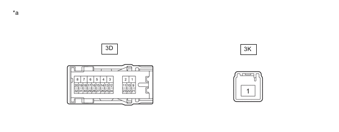
*a Component without harness connected
(Instrument Panel Junction Block Assembly)
- -
-
Disconnect the 3D instrument panel junction block assembly connector.
-
Measure the resistance according to the value(s) in the table below.
Standard Resistance Tester Connection Condition Specified Condition 3K-1 - 3D-24 Always Below 1 Ω 3K-1 - 3D-25 Always Below 1 Ω Result Proceed to OK NG
NG
REPLACE INSTRUMENT PANEL JUNCTION BLOCK ASSEMBLY Click here
OK
-
-
CHECK HARNESS AND CONNECTOR (NO. 1 INTERIOR ILLUMINATION LIGHT ASSEMBLY - INSTRUMENT PANEL JUNCTION BLOCK ASSEMBLY)
-
Disconnect the I5 No. 1 interior illumination light assembly LH (footwell light LH) connector.
-
Disconnect the I4 No. 1 interior illumination light assembly RH (footwell light RH) connector.
-
Measure the resistance according to the value(s) in the table below.
Standard Resistance Tester Connection Condition Specified Condition I5-2 (B) - 3D-25 Always Below 1 Ω I4-2 (B) - 3D-24 Always Below 1 Ω I5-2 (B) or 3D-25 - Body ground Always 10 kΩ or higher I4-2 (B) or 3D-24 - Body ground Always 10 kΩ or higher Result Proceed to OK NG
NG
REPAIR OR REPLACE HARNESS OR CONNECTOR
OK
-
-
CHECK HARNESS AND CONNECTOR (NO. 1 INTERIOR ILLUMINATION LIGHT ASSEMBLY - INSTRUMENT PANEL JUNCTION BLOCK ASSEMBLY)
-
Disconnect the 3A instrument panel junction block assembly connector.
-
Measure the resistance according to the value(s) in the table below.
Standard Resistance Tester Connection Condition Specified Condition I5-1 (L) - 3A-37 Always Below 1 Ω I4-1 (L) - 3A-36 Always Below 1 Ω I5-1 (L) or 3A-37 - Body ground Always 10 kΩ or higher I4-1 (L) or 3A-36 - Body ground Always 10 kΩ or higher Result Proceed to OK NG
NG
REPAIR OR REPLACE HARNESS OR CONNECTOR
OK
-
-
INSPECT INSTRUMENT PANEL JUNCTION BLOCK ASSEMBLY
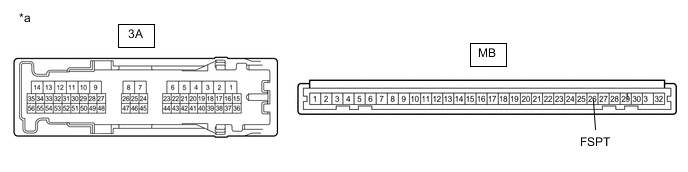
*a Component without harness connected
(Instrument Panel Junction Block Assembly)
- -
-
Remove the instrument panel junction block assembly.
-
Remove the main body ECU (multiplex network body ECU) from the instrument panel junction block assembly.
-
Measure the resistance according to the value(s) in the table below.
Standard Resistance Tester Connection Condition Specified Condition 3A-37 - MB-26 (FSPT) Always Below 1 Ω 3A-36 - MB-26 (FSPT) Always Below 1 Ω Result Proceed to OK NG
OK
REPLACE MAIN BODY ECU (MULTIPLEX NETWORK BODY ECU) Click here
NG
REPLACE INSTRUMENT PANEL JUNCTION BLOCK ASSEMBLY Click here
-