LIGHTING SYSTEM Front Door Courtesy Switch Circuit
DESCRIPTION
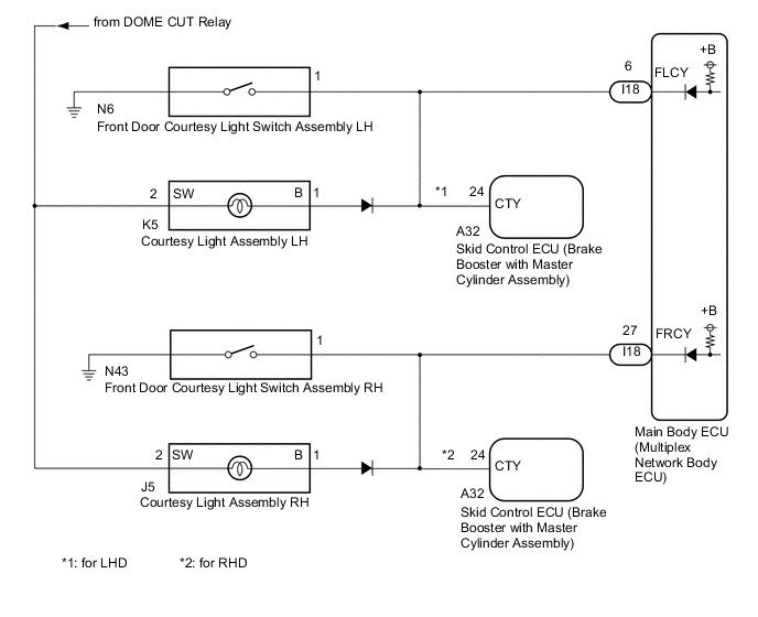
The main body ECU (multiplex network body ECU) detects the condition of the front door courtesy light switch assembly.
WIRING DIAGRAM
CAUTION / NOTICE / HINT
Note
Before replacing the main body ECU (multiplex network body ECU), refer to Service Bulletin.
PROCEDURE
-
READ VALUE USING GTS
-
Connect the GTS to the DLC3.
-
Turn the power switch on (IG).
-
Turn the GTS on.
-
Enter the following menus: Body Electrical / Main Body / Data List.
-
Read the Data List according to the display on the GTS.
Body Electrical > Main Body > Data ListTester Display Measurement Item Range Normal Condition Diagnostic Note FR Door Courtesy SW Front door courtesy light switch assembly RH signal OFF or ON OFF: Front door RH closed
ON: Front door RH open
- FL Door Courtesy SW Front door courtesy light switch assembly LH signal OFF or ON OFF: Front door LH closed
ON: Front door LH open
-
Body Electrical > Main Body > Data ListTester Display FR Door Courtesy SW FL Door Courtesy SW OK Normal conditions listed above are displayed. Result Result Proceed to OK A "FR Door Courtesy SW" is not normal B "FL Door Courtesy SW" is not normal C
A 
PROCEED TO NEXT SUSPECTED AREA SHOWN IN PROBLEM SYMPTOMS TABLE Click here
C 
INSPECT FRONT DOOR COURTESY LIGHT SWITCH ASSEMBLY LH Click here
B 
-
-
INSPECT FRONT DOOR COURTESY LIGHT SWITCH ASSEMBLY RH
-
Remove the front door courtesy light switch assembly RH.
-
Inspect the front door courtesy light switch assembly RH.
Result Proceed to OK NG
NG
REPLACE FRONT DOOR COURTESY LIGHT SWITCH ASSEMBLY RH Click here
OK
-
-
CHECK HARNESS AND CONNECTOR (FRONT DOOR COURTESY LIGHT SWITCH ASSEMBLY RH - MAIN BODY ECU (MULTIPLEX NETWORK BODY ECU))
-
for LHD
-
Disconnect the I18 main body ECU (multiplex network body ECU) connector.
-
Disconnect the J5 courtesy light assembly RH connector.
-
Measure the resistance according to the value(s) in the table below.
Standard Resistance Tester Connection Condition Specified Condition N43-1 - I18-27 (FRCY) Always Below 1 Ω N43-1, I18-27 (FRCY) or J5-1 (B) - Body ground Always 10 kΩ or higher
-
-
for RHD
-
Disconnect the I18 main body ECU (multiplex network body ECU) connector.
-
Disconnect the J5 courtesy light assembly RH connector.
-
Disconnect the A32 skid control ECU (brake booster with master cylinder assembly) connector.
-
Measure the resistance according to the value(s) in the table below.
Standard Resistance Tester Connection Condition Specified Condition N43-1 - I18-27 (FRCY) Always Below 1 Ω N43-1, I18-27 (FRCY), J5-1 (B) or A32-24 (CTY) - Body ground Always 10 kΩ or higher
Result Proceed to OK NG -
OK
REPLACE MAIN BODY ECU (MULTIPLEX NETWORK BODY ECU) Click here
NG
REPAIR OR REPLACE HARNESS OR CONNECTOR
-
-
INSPECT FRONT DOOR COURTESY LIGHT SWITCH ASSEMBLY LH
-
Remove the front door courtesy light switch assembly LH.
-
Inspect the front door courtesy light switch assembly LH.
Result Proceed to OK NG
NG
REPLACE FRONT DOOR COURTESY LIGHT SWITCH ASSEMBLY LH Click here
OK
-
-
CHECK HARNESS AND CONNECTOR (FRONT DOOR COURTESY LIGHT SWITCH ASSEMBLY LH - MAIN BODY ECU (MULTIPLEX NETWORK BODY ECU))
-
for LHD
-
Disconnect the I18 main body ECU (multiplex network body ECU) connector.
-
Disconnect the K5 courtesy light assembly LH connector.
-
Disconnect the A32 skid control ECU (brake booster with master cylinder assembly) connector.
-
Measure the resistance according to the value(s) in the table below.
Standard Resistance Tester Connection Condition Specified Condition N6-1 - I18-6 (FLCY) Always Below 1 Ω N6-1, I18-6 (FLCY), K5-1 (B) or A32-24 (CTY) - Body ground Always 10 kΩ or higher
-
-
for RHD
-
Disconnect the I18 main body ECU (multiplex network body ECU) connector.
-
Disconnect the K5 courtesy light assembly LH connector.
-
Measure the resistance according to the value(s) in the table below.
Standard Resistance Tester Connection Condition Specified Condition N6-1 - I18-6 (FLCY) Always Below 1 Ω N6-1, I18-6 (FLCY) or K5-1 (B) - Body ground Always 10 kΩ or higher
Result Proceed to OK NG -
OK
REPLACE MAIN BODY ECU (MULTIPLEX NETWORK BODY ECU) Click here
NG
REPAIR OR REPLACE HARNESS OR CONNECTOR
-