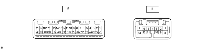
METER / GAUGE SYSTEM TERMINALS OF ECU
-
COMBINATION METER ASSEMBLY (METER CIRCUIT PLATE)
-
Measure the voltage and resistance and check for pulses according to the value(s) in the table below.
Terminal No. (Symbol) Wiring Color Terminal Description Condition Specified Condition I6-1 (MSM+) - Body ground LG - Body ground Steering pad switch assembly signal Power switch on (IG), enter, back and trip switches on steering pad switch assembly not pushed 4.8 to 5.2 V I6-2 (MSTI) - Body ground L - Body ground Steering pad switch assembly signal Power switch on (IG), up, down, right and left switches on steering pad switch assembly not pushed 4.8 to 5.2 V I6-3 (E2) - Body ground P - Body ground Ground Always Below 1 V I6-6 (INT) - Body ground LG - Body ground Tire pressure warning reset signal
-
Power switch on (IG)
-
Steering pad switch assembly operated, "TPMS" selected on the multi-information display and "ENTER" switch (steering pad switch assembly) pressed and held
Below 1.5 V
-
Power switch on (IG)
-
"ENTER" switch (steering pad switch assembly) off
8 to 15 V I6-8 (S) - Body ground GR - Body ground Oil pressure signal Engine started 11 to 14 V Engine not started Below 1 V I6-10 (RRSB) - Body ground P - Body ground Rear seat belt buckle switch RH signal Power switch on (IG), rear seat belt RH unfastened Below 1 V Power switch on (IG), rear seat belt RH fastened 11 to 14 V I6-12 (RLSB) - Body ground GR - Body ground Rear seat belt buckle switch LH signal Power switch on (IG), rear seat belt LH unfastened Below 1 V Power switch on (IG), rear seat belt LH fastened 11 to 14 V I6-13 (PODS) - Body ground*2 G - Body ground Occupant detection sensor signal Power switch on (IG), front passenger seat not occupied Below 1 V Power switch on (IG), front passenger seat occupied 11 to 14 V I6-14 (PBKL) - Body ground*2 L - Body ground Front passenger seat belt buckle switch signal Power switch on (IG), front passenger seat belt unfastened Below 1 V Power switch on (IG), front passenger seat belt fastened 11 to 14 V I6-15 (OIL) - Body ground P - Body ground Engine oil level signal Power switch on (IG), engine oil level not low 11 to 14 V Power switch on (IG), engine oil level low Below 1 V I6-16 (WLVL) - Body ground*1 BE - Body ground Washer fluid level signal Power switch on (IG), washer fluid level not low 11 to 14 V Power switch on (IG), washer fluid level low Below 1 V I6-19 (+S) - Body ground B - Body ground Speed signal for other systems (Output) Power switch on (IG), wheel being rotated Pulse generation (See waveform 1) I6-20 (SI) - Body ground LG - Body ground Speed signal for other system (Input) Power switch on (IG), wheel being rotated Pulse generation (See waveform 1) I6-21 (IG+) - Body ground G - Body ground Power switch signal Power switch off Below 1 V Power switch on (IG) 11 to 14 V I6-22 (B) - Body ground
-
W - Body ground*3
-
GR - Body ground*4
Auxiliary battery Power switch off 11 to 14 V I6-23 (TWS3) - Body ground SB - Body ground Engine coolant temperature sensor signal Idling, engine coolant temperature 75 to 100°C (167 to 212°F) 0.2 to 0.6 V I6-24 (TR) - Body ground*4 L - Body ground Light control rheostat switch signal Power switch on (IG), up switch and down switch (combination switch assembly) not pushed 4.6 to 5.3 V Power switch on (IG), up switch (combination switch assembly) pushed Below 1 V Power switch on (IG), down switch (combination switch assembly) pushed 2 to 3.6 V I6-26 (CANH) - Body ground V - Body ground CAN communication line - - I6-27 (CANL) - Body ground W - Body ground CAN communication line - - I6-28 (ES) - Body ground W-B - Body ground Ground Always Below 1 Ω I6-29 (FR) - I6-30 (FE&B) L - BE Fuel level signal Power switch on (IG), fuel level full → low (fuel level warning light on) Pulse generation (See waveform 5) I6-31 (FV) - Body ground V - Body ground Fuel sender gauge (Power source) Power switch on (IG) 4.5 to 5.5 V I6-32 (IND) - Body ground*5 L - Body ground Heated steering wheel indicator light signal Power switch on (IG), heated steering wheel system on Below 3 V Power switch on (IG), heated steering wheel system off 11 to 14 V I6-33 (MSCH) - Body ground B - Body ground Local bus communication line - - I6-34 (MSCL) - Body ground W - Body ground Local bus communication line - - I6-37 (LST1) - Body ground*6 R - Body ground Fuel lid operation signal "Please Wait Now Opening" displayed on multi-information display Pulse generation (See waveform 2) "Refuel Ready" displayed on multi-information display Pulse generation (See waveform 3) "Close Fuel Lid" displayed on multi-information display Pulse generation (See waveform 4) Power switch on (IG) 11 to 14 V I6-40 (EP) - Body ground W-B - Body ground Ground Always Below 1 Ω I7-1 (B) - Body ground G - Body ground Auxiliary battery Power switch off 11 to 14 V I7-2 (LP) - Body ground R - Body ground Security warning signal Security warning light off 11 to 14 V Security warning light blinking Below 1 V ←→ 11 to 14 V I7-3 (PAON) - Body ground W - Body ground Passenger airbag ON indicator light signal Power switch on (IG), passenger airbag ON indicator light on Below 1 V Power switch on (IG), passenger airbag ON indicator light off 11 to 14 V I7-4 (P-AB) - Body ground B - Body ground Passenger airbag OFF indicator light signal Power switch on (IG), passenger airbag OFF indicator light on Below 1 V Power switch on (IG), passenger airbag OFF indicator light off 11 to 14 V I7-5 (ER) - Body ground GR - Body ground RH turn signal switch signal Power switch on (IG), RH turn signal switch off 11 to 14 V Power switch on (IG), RH turn signal switch on Below 1 V I7-6 (LR) - Body ground SB - Body ground Front and side turn signal light RH signal Power switch on (IG), RH turn indicator light off Below 1 V Power switch on (IG), RH turn indicator light blinking 11 to 14 V ←→ Below 1 V I7-7 (TRNR) - Body ground SB - Body ground Rear turn signal light RH signal Power switch on (IG), RH turn indicator light off Below 1 V Power switch on (IG), RH turn indicator light blinking 11 to 14 V ←→ Below 1 V I7-9 (SW) - Body ground BE - Body ground Turn signal switch signal Power switch on (IG), LH and RH turn signal switch off 11 to 14 V Power switch on (IG), LH or RH turn signal switch on Below 1 V I7-10 (HAZ) - Body ground L - Body ground Hazard warning signal switch signal Hazard warning signal switch off 11 to 14 V Hazard warning signal switch on Below 1 V I7-11 (EL) - Body ground W - Body ground LH turn signal switch signal Power switch on (IG), LH turn signal switch off 11 to 14 V Power switch on (IG), LH turn signal switch on Below 1 V I7-12 (LL) - Body ground BE - Body ground Front and side turn signal light LH signal Power switch on (IG), LH turn indicator light off Below 1 V Power switch on (IG), LH turn indicator light blinking 11 to 14 V ←→ Below 1 V I7-13 (TRNL) - Body ground BE - Body ground Rear turn signal light LH signal Power switch on (IG), LH turn indicator light off Below 1 V Power switch on (IG), LH turn indicator light blinking 11 to 14 V ←→ Below 1 V
-
*1: w/ Washer Fluid Level Warning
-
*2: w/o Occupant Classification System
-
*3: for LHD
-
*4: for RHD
-
*5: w/ Heated Steering Wheel System
-
*6: w/ Canister Pump Module
-
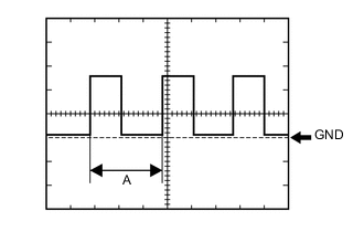
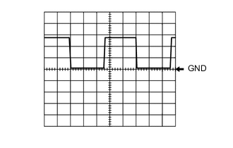
Waveform 1:
Item Condition Tester Connection
-
I6-19 (+S) - Body ground
-
I6-20 (SI) - Body ground
Tool setting 5 V/DIV., 20 ms./DIV. Condition Power switch on (IG), wheel being rotated Tech Tips
When the system is functioning normally, one wheel revolution generates 4 pulses. As the vehicle speed increases, the width indicated by (A) in the illustration narrows.
-
-
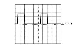
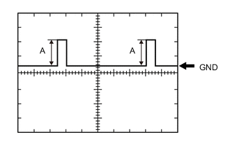
Waveform 2:
Item Condition Tester Connection I6-37 (LST1) - Body ground Tool setting 5 V/DIV., 20 ms./DIV. Condition "Please Wait Now Opening" displayed on multi-information display Tech Tips
This waveform is output when the internal pressure of the fuel tank is higher than the ambient pressure when the fuel lid opener switch is operated.
-
Waveform 3:
Item Condition Tester Connection I6-37 (LST1) - Body ground Tool setting 5 V/DIV., 20 ms./DIV. Condition "Refuel Ready" displayed on multi-information display -
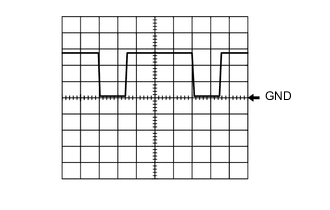
Waveform 4:
Item Condition Tester Connection I6-37 (LST1) - Body ground Tool setting 5 V/DIV., 20 ms./DIV. Condition "Close Fuel Lid" displayed on multi-information display Tech Tips
This waveform is output when the fuel lid opener switch is operated if the fuel lid is open and any of the following conditions are met:
-
The vehicle has been driven for 1 km (0.6 mile) or more at a speed of 50 km/h (31 mph) or more.
-
30 minutes or more have elapsed since the fuel lid opener switch was operated.
-
-
Waveform 5:
Item Condition Tester Connection I6-29 (FR) - I6-30 (FE&B) Tool setting 5 V/DIV., 20 ms./DIV. Vehicle condition Power switch on (IG), fuel level full → low (fuel level warning light on) Tech Tips
-
(A) will depending on the fuel level
-
Fuel level full → low (fuel level warning light on) (4.1 to 4.4 V → below 1 V)
-
-
-