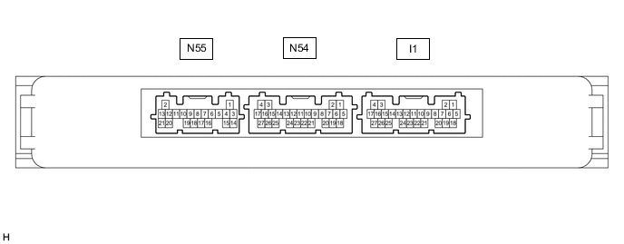
ENTRY AND START SYSTEM(for Start Function) TERMINALS OF ECU
-
CHECK CERTIFICATION ECU (SMART KEY ECU ASSEMBLY)
-
Disconnect the N54 and I1 certification ECU (smart key ECU assembly) connectors.
-
Measure the voltage and resistance according to the value(s) in the table below.
Tech Tips
Measure the values on the wire harness side with the connector disconnected.
Terminal No. (Symbol) Input/Output Wiring Color Terminal Description Condition Specified Condition Related Data List Item N54-25 (STP1) - Body ground Input SB - Body ground Stop light switch signal Brake pedal depressed → Brake pedal released 9 V or higher → 1 V or less Stop Light Switch1 I1-4 (+B) - I1-18 (E) Input GR - W-B Power source Power switch off 11 to 14 V - I1-18 (E) - Body ground - W-B - Body ground GND Always Below 1 Ω - I1-21 (SSW2) - Body ground Input G - Body ground SSW2 contact signal
Tech Tips
Backup for SSW1. Behaves the same way as SSW1.
Power switch pushed → Power switch not pushed Below 15 Ω → 10 kΩ or higher Start Switch2 I1-23 (SSW1) - Body ground Input BE - Body ground SSW1 contact signal Power switch pushed → Power switch not pushed Below 15 Ω → 10 kΩ or higher Start Switch1 I1-16 (ACCD) - Body ground Output R - Body ground ACC signal 20°C (68°F) 285.71 to 428.57 Ω ACC Relay Monitor I1-17 (IG1D) - Body ground Output L - Body ground IG signal 20°C (68°F) 55.04 to 88.24 Ω IG Relay Monitor (Outside) I1-19 (SPD) - Body ground Input GR - Body ground Vehicle speed signal Always 30 kΩ or higher Vehicle Speed Signal -
Reconnect the N54 and I1 certification ECU (smart key ECU assembly) connectors.
-
Measure the voltage and check for pulses according to the value(s) in the table below.
Terminal No. (Symbol) Input/Output Wiring Color Terminal Description Condition Specified Condition Related Data List Item N54-25 (STP1) - I1-18 (E) Input SB - W-B Stop light switch signal Brake pedal released → Brake pedal depressed 1 V or less → 9 V or higher Stop Light Switch1 I1-22 (P) - I1-18 (E) Input V - W-B P position signal Power switch on (IG), park (P) selected Pulse generation
(See waveform 1)
Shift P Signal I1-21 (SSW2) - I1-18 (E) Input G - W-B SSW2 contact signal
Tech Tips
Backup for SSW1. Behaves the same way as SSW1.
Power switch not pushed → Power switch pushed 9 V or higher → 1 V or less Start Switch2 I1-23 (SSW1) - I1-18 (E) Input BE - W-B SSW1 contact signal Power switch not pushed → Power switch pushed 9 V or higher → 1 V or less Start Switch1 I1-16 (ACCD) - I1-18 (E) Output R - W-B ACC signal Power switch off → Power switch on (ACC) 1 V or less → 8.5 V or higher ACC Relay Monitor I1-17 (IG1D) - I1-18 (E) Output L - W-B IG signal Power switch on (ACC) → Power switch on (IG) 1 V or less → 9 V or higher IG Relay Monitor (Outside) I1-19 (SPD) - I1-18 (E) Input GR - W-B Vehicle speed signal Vehicle being driven at approx. 5 km/h (3 mph) Pulse generation
(See waveform 2)
Vehicle Speed Signal I1-27 (ST2) - I1-18 (E) Output B - W-B STSW signal With the brake pedal depressed, the power switch is pressed and held → After approx. 3 sec. has elapsed, the power switch is released 8.5 V or higher → 1 V or less - I1-3 (IGB) - I1-18 (E) Output LG - W-B IGB signal Power switch off → Power switch on (IG) 1 V or less → 8.5 V or higher - N55-2 (IGBD) - I1-18 (E) Output P - W-B Relay operation signal Power switch off → Power switch on (IG) 1 V or less → 8.5 V or higher - I1-8 (CLG5) - I1-18 (E) Output SB - W-B Output to No. 1 indoor electrical key antenna assembly (front floor) Procedure:
-
Power switch off
-
Electrical key transmitter sub-assembly not inside vehicle
-
Within 30 seconds of closing any door
Pulse generation
(See waveform 3)
Overhead + Front Room (key diagnostic mode) I1-9 (CG5B) - I1-18 (E) Output GR - W-B Output to No. 1 indoor electrical key antenna assembly (front floor) (terminal on opposite side of component from CLG5 output terminal) Procedure:
-
Power switch off
-
Electrical key transmitter sub-assembly not inside vehicle
-
Within 30 seconds of closing any door
Pulse generation
(See waveform 3)
Overhead + Front Room (key diagnostic mode) N54-5 (CLG6) - I1-18 (E) Output GR - W-B Output to No. 2 indoor electrical key antenna assembly (rear floor) Procedure:
-
Power switch off
-
Electrical key transmitter sub-assembly not inside vehicle
-
Within 30 seconds of closing any door
Pulse generation
(See waveform 3)
Overhead + Rear Room (key diagnostic mode) N54-6 (CG6B) - I1-18 (E) Output BR - W-B Output to No. 2 indoor electrical key antenna assembly (rear floor) (terminal on opposite side of component from CLG6 output terminal) Procedure:
-
Power switch off
-
Electrical key transmitter sub-assembly not inside vehicle
-
Within 30 seconds of closing any door
Pulse generation
(See waveform 3)
Overhead + Rear Room (key diagnostic mode) N54-11 (CLG7) - I1-18 (E) Output G - W-B Output to No. 3 indoor electrical key antenna assembly (inside luggage compartment) Procedure:
-
Power switch off
-
Electrical key transmitter sub-assembly not inside vehicle
-
Within 30 seconds of closing any door
Pulse generation
(See waveform 3)
Overhead + Back Door (inside) (key diagnostic mode) N54-10 (CG7B) - I1-18 (E) Output R - W-B Output to No. 3 indoor electrical key antenna assembly (inside luggage compartment) (terminal on opposite side of component from CLG7 output terminal) Procedure:
-
Power switch off
-
Electrical key transmitter sub-assembly not inside vehicle
-
Within 30 seconds of closing any door
Pulse generation
(See waveform 3)
Overhead + Back Door (inside) (key diagnostic mode) N54-7 (WCSW) - I1-18 (E)* Output L - W-B Wireless charger system stop signal Procedure:
-
Power switch off
-
Electrical key transmitter sub-assembly inside vehicle
-
Power switch off → on (ACC)
Below 1 V → 4.5 to 6 V
(For 1 second after Power switch on (ACC))
-
-
*: w/ Wireless Charging System
-
-
Using an oscilloscope, check the waveform of the ECU.
Note
The oscilloscope waveform shown in the illustration is an example for reference only. Noise, chattering, etc. are not shown.
-
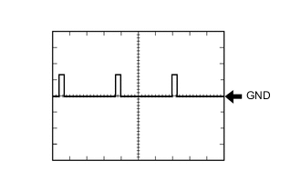
Waveform 1
Item Content Tester Connection I1-22 (P) - I1-18(E) Tool Setting 10 V/DIV., 10 ms/DIV. Condition Power switch on (IG), P position -
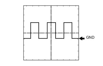
Waveform 2
Item Content Tester Connection I1-19 (SPD) - I1-18(E) Tool Setting 5 V/DIV., 20 ms/DIV. Condition Vehicle being driven at approx. 5 km/h (3 mph) Tech Tips
The wavelength becomes shorter as the vehicle speed increases.
-
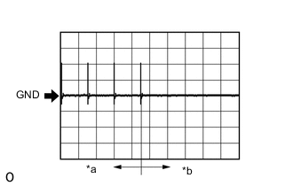
*a For 30 seconds after any door closed *b After 30 seconds or more have elapsed since any door closed Waveform 3
Item Content Tester Connection I1-8 (CLG5) - I1-18 (E)
I1-9 (CG5B) - I1-18 (E)
N54-5 (CLG6) - I1-18 (E)
N54-6 (CG6B) - I1-18 (E)
N54-11 (CLG7) - I1-18 (E)
N54-10 (CG7B) - I1-18 (E)
Tool Setting 2 V/DIV., 500 ms/DIV. Condition Procedure:
-
Power switch off
-
Electrical key transmitter sub-assembly not inside vehicle
-
Within 30 seconds of closing any door
-
-
-
-
CHECK ID CODE BOX (IMMOBILISER CODE ECU)
-
CHECK HYBRID VEHICLE CONTROL ECU
-
CHECK POWER SWITCH