REAR DOOR LOCK INSTALLATION
CAUTION / NOTICE / HINT
Tech Tips
-
Use the same procedure for the RH side and LH side.
-
The following procedure is for the LH side.
PROCEDURE
-
PRECAUTION
Note
After turning the power switch off, waiting time may be required before disconnecting the cable from the negative (-) auxiliary battery terminal. Therefore, make sure to read the disconnecting the cable from the negative (-) auxiliary battery terminal notices before proceeding with work.
-
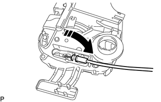
INSTALL REAR DOOR INSIDE LOCKING CABLE ASSEMBLY (w/o Double Locking System)
-
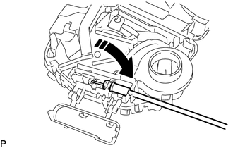

Install in this Direction Install the rear door inside locking cable assembly as shown in the illustration.
-
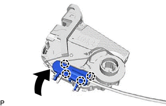
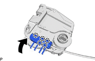
Engage the 4 claws to close the cover as shown in the illustration.
-
-
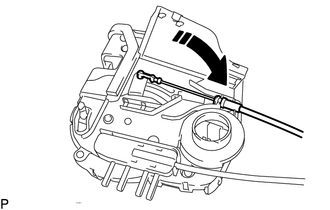
INSTALL REAR DOOR LOCK REMOTE CONTROL CABLE ASSEMBLY (w/o Double Locking System)
-
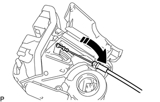
Install in this Direction Install the rear door lock remote control cable assembly as shown in the illustration.
-
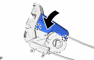
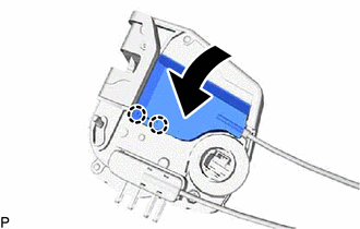
Engage the 2 claws to close the cover as shown in the illustration.
-
-
INSTALL REAR DOOR INSIDE LOCKING CABLE ASSEMBLY (w/ Double Locking System)
-
Install in this Direction Install the rear door inside locking cable assembly as shown in the illustration.
-
Engage the 5 claws to close the cover as shown in the illustration.
-
-
INSTALL REAR DOOR LOCK REMOTE CONTROL CABLE ASSEMBLY (w/ Double Locking System)
-
Install in this Direction Install the rear door lock remote control cable assembly as shown in the illustration.
-
Engage the 2 claws to close the cover as shown in the illustration.
-
-
INSTALL REAR DOOR LOCK WITH MOTOR ASSEMBLY
Note
-
When reusing a removed rear door lock with motor assembly, replace the door lock wiring harness seal with a new one.
-
Do not allow grease or dust to adhere to the door lock wiring harness seal installation surface.
-
Reusing a door lock wiring harness seal or using a damaged door lock wiring harness seal may cause water ingress. This may result in a malfunction of the rear door lock with motor assembly.
-
Apply MP grease to the sliding parts of the rear door lock with motor assembly.
-
When reusing the rear door lock with motor assembly:
-
Install a new door lock wiring harness seal to the rear door lock with motor assembly.
-
-
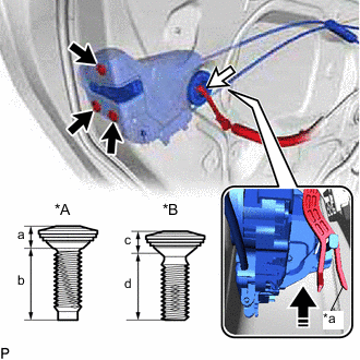
*A for Type A *B for Type B *a Release Plate Install in this Direction Connect the rear door lock with motor assembly to the release plate of the rear door outside handle frame sub-assembly, and set it to the rear door panel.
Tech Tips
Make sure that the release plate of the rear door outside handle frame sub-assembly is securely connected to the rear door lock with motor assembly.
-
Using a T30 "TORX" socket wrench, install the rear door lock with motor assembly with the 3 screws.
- Torque:
- for Type A
- 5.5 N*m { 56 kgf*cm, 49 in.*lbf }
- for Type B
- 5.0 N*m { 51 kgf*cm, 44 in.*lbf }
Area Measurement a 5.25 to 5.55 mm (0.207 to 0.219 in.) b 16.5 to 17.1 mm (0.650 to 0.673 in.) c 5.9 to 6.5 mm (0.232 to 0.256 in.) d 14.0 to 15.0 mm (0.551 to 0.591 in.) -
Connect the connector.
-
-
INSTALL REAR DOOR GLASS SUB-ASSEMBLY
-
INSTALL REAR DOOR QUARTER WINDOW GLASS
-
INSTALL REAR DOOR WINDOW DIVISION BAR SUB-ASSEMBLY
-
CONNECT REAR DOOR WEATHERSTRIP
-
Connect the rear door weatherstrip.
-
-
INSTALL REAR DOOR GLASS RUN
-
INSTALL REAR DOOR NO. 2 SERVICE HOLE COVER
-
INSTALL REAR DOOR PANEL PROTECTOR
-
INSTALL REAR DOOR SERVICE HOLE COVER
-
INSTALL REAR DOOR INNER GLASS WEATHERSTRIP WITH REAR DOOR NO. 2 VENT SEAL
-
INSTALL REAR DOOR TRIM BOARD SUB-ASSEMBLY
-
INSTALL REAR POWER WINDOW REGULATOR SWITCH ASSEMBLY WITH REAR DOOR UPPER ARMREST BASE PANEL
-
INSTALL REAR ARMREST ASSEMBLY
-
INSTALL REAR DOOR INSIDE HANDLE BEZEL PLUG
-
CONNECT CABLE TO NEGATIVE AUXILIARY BATTERY TERMINAL
Note
When disconnecting the cable, some systems need to be initialized after the cable is reconnected.
-
INITIALIZE POWER WINDOW CONTROL SYSTEM
-
INSPECT POWER WINDOW OPERATION