SOLAR CHARGING SYSTEM Solar Charging System Power Generation Malfunction
DESCRIPTION
Due to the properties of the No. 1 roof window glass sub-assembly, if the No. 1 roof window glass sub-assembly is malfunctioning or there is an open in the wire harness between the No. 1 roof window glass sub-assembly and solar energy control unit, the solar energy control unit may not be able to detect the malfunction as it is unable to determine if electricity is not being generated due to a malfunction or the absence of sufficient sunlight. Therefore, even if a malfunction is not detected, there may still be a malfunction. Even if the solar roof is not malfunctioning, due to the environment (seasons, shadows, etc.) or system state, power may not be able to be generated. It is necessary to confirm any environment causes based on the interview with the customer or the on-site inspection, etc. Depending on the state of the system, it is possible to make approximate judgments based on the Vehicle Control History.
CAUTION / NOTICE / HINT
CAUTION:
-

Before performing any of the following operations, take precautions to prevent electric shock by turning the power switch off, wearing insulated gloves, and removing the service plug grip.
-
Inspecting the high-voltage system
-
Disconnecting the low voltage connector of the inverter with converter assembly
-
Disconnecting the low voltage connector of the HV battery
-
Disconnecting the low voltage connector of the electric vehicle charger assembly.
-
Disconnecting the low voltage connector of the solar energy control unit.
-

To prevent electric shock, make sure to remove the service plug grip to cut off the high voltage circuit before servicing the vehicle.
-

After removing the service plug grip from the HV battery, put it in your pocket to prevent other technicians from accidentally reconnecting it while you are working on the high-voltage system.
-
*a Without waiting for 10 minutes After removing the service plug grip, wait for at least 10 minutes before touching any of the high-voltage connectors or terminals. After waiting for 10 minutes, check the voltage at the terminals in the inspection point in the inverter with converter assembly. The voltage should be 0 V before beginning work.
Tech Tips
Waiting for at least 10 minutes is required to discharge the high-voltage capacitor inside the inverter with converter assembly.
Note
After turning the power switch off, waiting time may be required before disconnecting the cable from the negative (-) auxiliary battery terminal. Therefore, make sure to read the disconnecting the cable from the negative (-) auxiliary battery terminal notices before proceeding with work.
PROCEDURE
-
CHECK DTC OUTPUT
-
Connect the GTS to the DLC3.
-
Turn the power switch on (IG).
-
Turn the GTS on.
-
Enter the following menus: Powertrain / Hybrid Control, HV Battery, Plug-in Control / Trouble Codes.
-
Check DTCs.
Powertrain > Hybrid Control > Trouble Codes
Powertrain > HV Battery > Trouble Codes
Powertrain > Plug-in Control > Trouble CodesResult Result Proceed to DTCs are not output. A DTCs are output. B -
Turn the power switch off.
B 
GO TO DTC CHART
A 
-
-
CHECK DTC OUTPUT (HEALTH CHECK)
-
Connect the GTS to the DLC3.
-
Turn the power switch on (IG).
-
Turn the GTS on.
-
Enter the following menus: Health Check.
-
Check DTCs.
Result Result Proceed to No DTCs are output. A DTCs are output. B -
Turn the power switch off.
B
GO TO DTC CHART
A
-
-
INSPECT NO.1 ROOF WINDOW GLASS SUB-ASSEMBLY
CAUTION:
Be sure to wear insulated gloves.
-
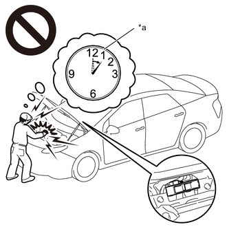
Park the vehicle in an area where the solar radiation will be steady.
-
Ensure that the following vehicle conditions are met.
Weather Clear or mostly clear and sunny Time Between 11:00 and 14:00 Place An area where sunlight strikes the solar roof directly Tech Tips
-
Make sure no part of the solar roof is shaded.
-
If the solar roof is dirty, clean it.
-
-
Disconnect the cable from the negative (-) auxiliary battery terminal.
-
Remove the service plug grip.
-
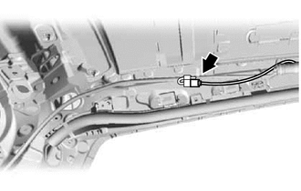
Remove the rear seat cushion assembly LH.
-
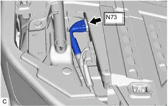
Disconnect the N73 solar energy control unit connector.
-
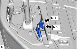
Disconnect the N71 and N72 solar energy control unit connectors.
-
Measure the voltage according to the value(s) in the table below.
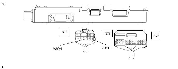
*a Rear view of wire harness connector
(to Solar Energy Control Unit)
- - Standard Voltage Tester Connection Specified Condition N73-5 (VSOP) - N73-7 (VSON) 27 V or higher -
Reconnect the N71 and N72 solar energy control unit connectors.
-
Reconnect the N73 solar energy control unit connector.
-
Install the rear seat cushion assembly LH.
-
Install the service plug grip.
-
Connect the cable to the negative (-) auxiliary battery terminal.
Result Proceed to OK NG
NG 
CHECK CONNECTOR CONNECTION CONDITION (NO. 1 ROOF WINDOW GLASS SUB-ASSEMBLY CONNECTOR) Click here
OK
-
-
CHECK SOLAR ENERGY CONTROL UNIT
CAUTION:
Be sure to wear insulated gloves.
-
Park the vehicle in an area where the solar radiation will be steady.
Weather Clear or mostly clear and sunny Time Between 11:00 and 14:00 Place An area where sunlight strikes the solar roof directly Tech Tips
-
Make sure no part of the solar roof is shaded.
-
If the solar roof is dirty, clean it.
-
-
Turn the power switch on (READY).
-
Leave the vehicle with the power switch on (READY) for a while and then check the energy generated by the solar charging system display on the multi-information display.
Specified Condition The value of the energy generated by the solar charging system display on the multi-information display increases 3 Wh or more. Tech Tips
The value of the energy generated by the solar charging system display on the multi-information display increases 3 Wh or more.
-
Turn the power switch off.
Result Proceed to OK NG
NG
REPLACE SOLAR ENERGY CONTROL UNIT Click here
OK
-
-
CHECK DATA (VEHICLE CONTROL HISTORY (SOLAR CHARGING SYSTEM))
-
Connect the GTS to the DLC3.
-
Turn the power switch on (IG).
-
Turn the GTS on.
-
Enter the following menus: Powertrain / Solar Charging Control / Utility / Vehicle Control History.
Powertrain > Solar Charging Control > UtilityTester Display Vehicle Control History -
Check for Vehicle Control History.
Result Result Proceed to Vehicle Control History is not stored. A Vehicle Control History is stored. B -
Turn the power switch off.
A
GO TO CAUSE ANALYSIS Click here
B
CONFIRM VEHICLE CONTROL HISTORY (SOLAR CHARGING SYSTEM) Click here
-
-
CHECK CONNECTOR CONNECTION CONDITION (NO. 1 ROOF WINDOW GLASS SUB-ASSEMBLY CONNECTOR)
-
Remove the roof headlining assembly.
-
Check the connection condition of the No. 1 roof window glass sub-assembly connector and the contact pressure of each terminal. Check the terminals for deformation, and check the connector for water ingress and foreign matter.
OK - The connector is connected securely. - The terminals are not deformed and are connected securely. - No water or foreign matter in the connector. Result Result Proceed to OK A NG (The connector is not connected securely.) B NG (The terminals are not making secure contact or are deformed, or water or foreign matter exists in the connector.) C -
Install the roof headlining assembly.
B
CONNECT SECURELY
C
REPAIR OR REPLACE HARNESS OR CONNECTOR
A
-
-
CHECK HARNESS AND CONNECTOR (SOLAR ENERGY CONTROL UNIT - NO. 1 ROOF WINDOW GLASS SUB-ASSEMBLY)
CAUTION:
Be sure to wear insulated gloves.
-
Remove the roof headlining assembly.
-
Disconnect the N69 No. 1 roof window glass sub-assembly connector.
-
Check that the service plug grip is not installed.
Note
After removing the service plug grip, do not turn the power switch on (READY), unless instructed by the repair manual because this may cause a malfunction.
-
Remove the rear seat cushion assembly LH.
-
Disconnect the N73 solar energy control unit connector.
-
Disconnect the N71 and N72 solar energy control unit connectors.
-
Measure the resistance according to the value(s) in the table below.
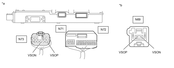
*a Rear view of wire harness connector
to Solar Energy Control Unit)
*b Front view of wire harness connector
(to No. 1 Roof Window Glass Sub-assembly)
Standard Resistance Tester Connection Condition Specified Condition N73-5 (VSOP) - N69-2 (VSOP) Power switch off Below 1 Ω N73-7 (VSON) - N69-1 (VSON) Power switch off Below 1 Ω N73-5 (VSOP) or N69-2 (VSOP) - Body ground and other terminals Power switch off 10 kΩ or higher N73-7 (VSON) or N69-1 (VSON) - Body ground and other terminals Power switch off 10 kΩ or higher -
Reconnect the N71 and N72 solar energy control unit connectors.
-
Reconnect the N73 solar energy control unit connector.
-
Install the rear seat cushion assembly LH.
-
Reconnect the N69 No. 1 roof window glass sub-assembly connector.
-
Install the roof headlining assembly.
Result Proceed to OK NG
OK
REPLACE ROOF WINDOW GLASS SUB-ASSEMBLY NO.1 Click here
NG
REPAIR OR REPLACE HARNESS OR CONNECTOR
-