SOLAR CHARGING SYSTEM, Diagnostic DTC:P1EC000, P1EC01E, P1EC200, P1EC21E, P1EC400, P1EC41E
| DTC Code | DTC Name |
|---|---|
| P1EC000 | Solar Charging Battery Block 1 Circuit Resistance Out of Range (Extreme) |
| P1EC01E | Solar Charging Battery Block 1 Circuit Resistance Out of Range |
| P1EC200 | Solar Charging Battery Block 2 Circuit Resistance Out of Range (Extreme) |
| P1EC21E | Solar Charging Battery Block 2 Circuit Resistance Out of Range |
| P1EC400 | Solar Charging Battery Block 3 Circuit Resistance Out of Range (Extreme) |
| P1EC41E | Solar Charging Battery Block 3 Circuit Resistance Out of Range |
DESCRIPTION
Refer to the description for DTC P1ED000.
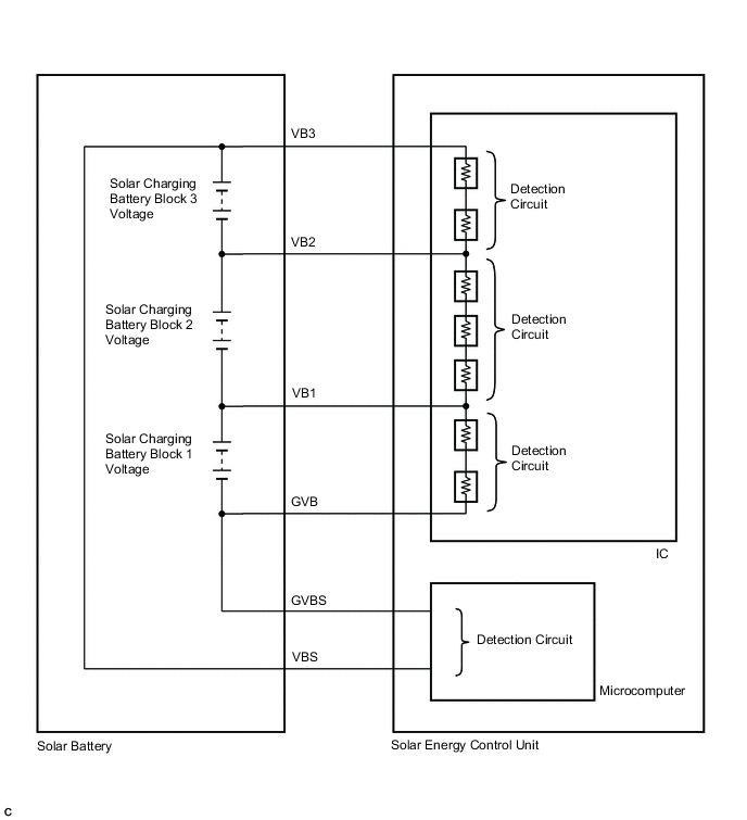
The solar energy control unit maintains the SOC (state of charge) of the solar battery within a certain range. The solar battery is composed of 3 modules, and each module consists of six 1.2 V cells in series. The solar energy control unit monitors the voltage of the solar battery at 3 locations.
| DTC No. | Detection Item | DTC Detection Condition | Trouble Area | Warning Indicate |
|---|---|---|---|---|
| P1EC000 | Solar Charging Battery Block 1 Circuit Resistance Out of Range (Extreme) | An internal malfunction of the solar battery is detected. The difference in internal resistance between the battery block 1 and 2 is excessively higher than the specified value. (1 trip detection logic) |
|
Solar Charging Warning Light: Comes on |
| P1EC01E | Solar Charging Battery Block 1 Circuit Resistance Out of Range | An internal malfunction of the solar battery is detected. The difference in internal resistance between the battery block 1 and 2 is higher than the specified value. (1 trip detection logic) |
|
Solar Charging Warning Light: Comes on |
| P1EC200 | Solar Charging Battery Block 2 Circuit Resistance Out of Range (Extreme) | An internal malfunction of the solar battery is detected. The difference in internal resistance between the battery block 2 and 3 is excessively higher than the specified value. (1 trip detection logic) |
|
Solar Charging Warning Light: Comes on |
| P1EC21E | Solar Charging Battery Block 2 Circuit Resistance Out of Range | An internal malfunction of the solar battery is detected. The difference in internal resistance between the battery block 2 and 3 is higher than the specified value. (1 trip detection logic) |
|
Solar Charging Warning Light: Comes on |
| P1EC400 | Solar Charging Battery Block 3 Circuit Resistance Out of Range (Extreme) | An internal malfunction of the solar battery is detected. The difference in internal resistance between the battery block 1 and 3 is excessively higher than the specified value. (1 trip detection logic) |
|
Solar Charging Warning Light: Comes on |
| P1EC41E | Solar Charging Battery Block 3 Circuit Resistance Out of Range | An internal malfunction of the solar battery is detected. The difference in internal resistance between the battery block 1 and 3 is higher than the specified value. (1 trip detection logic) |
|
Solar Charging Warning Light: Comes on |
| DTC No. | Data List |
|---|---|
| P1EC000 |
|
| P1EC01E | |
| P1EC200 | |
| P1EC21E | |
| P1EC400 | |
| P1EC41E |
| Data List | Voltage |
|---|---|
| Solar Charging Battery Block 1 Voltage | Approximately 8.2 V |
| Solar Charging Battery Block 2 Voltage | Approximately 8.2 V |
| Solar Charging Battery Block 3 Voltage | Approximately 8.2 V |
| Solar Charging Battery Block 1 Voltage Sensor Upper Side Voltage | Approximately 4.1 V |
| Solar Charging Battery Block 1 Voltage Sensor Under Side Voltage | Approximately 4.1 V |
| Solar Charging Battery Block 2 Voltage Sensor Upper Side Voltage | Approximately 2.7 V |
| Solar Charging Battery Block 2 Voltage Sensor Middle Side Voltage | Approximately 2.7 V |
| Solar Charging Battery Block 2 Voltage Sensor Under Side Voltage | Approximately 2.7 V |
| Solar Charging Battery Block 3 Voltage Sensor Upper Side Voltage | Approximately 4.1 V |
| Solar Charging Battery Block 3 Voltage Sensor Under Side Voltage | Approximately 4.1 V |
| Solar Charging Battery Charging and Discharging Voltage | Approximately 24.5 V |
| Solar Charging Battery Block Total Voltage | Approximately 24.5 V |
Tech Tips
Under normal conditions, the difference between the highest solar battery block voltage and lowest solar battery block voltage is approximately 1.0 V or less.
CONFIRMATION DRIVING PATTERN
Tech Tips
After completing repairs, clear the DTCs and then check that the vehicle has returned to normal by performing the following All Readiness check procedure.
-
Park the vehicle in an area where the solar radiation will be steady.
Weather Clear or mostly clear and sunny Time Between 11:00 and 14:00 Place An area where sunlight strikes the solar roof directly Tech Tips
-
Make sure no part of the solar roof is shaded.
-
If the solar roof is dirty, clean it.
-
-
Turn the power switch off and then disconnect the cable from the negative (-) auxiliary battery terminal.
-
Wait for 5 seconds or more, then disconnect the power source connector and then all other low voltage connectors the solar energy control unit.
-
Wait for 30 seconds or more, then connect the low voltage connectors of the solar energy control unit except the power source connector and then connect the power source connector.
-
Connect the cable to the negative (-) auxiliary battery terminal.
-
Turn the power switch on (IG), wait for 5 to 10 seconds, and then turn the power switch off.
Tech Tips
Make sure to turn the power switch off within 10 seconds.
-
Wait for 20 minutes and then check for DTCs to check that no DTCs have been stored.
Tech Tips
-
While waiting, the HV battery will be charged by the solar charging system. However, depending on certain conditions, charging may not be performed.
-
If the SOC of the HV battery is 90% or more, the HV battery will not be charged by the solar charging system.
-
If any of the following conditions is met, the HV battery will not be charged by the solar charging system:
-
The HV battery is charged via an external power source.
-
The power switch is on (ACC).
-
The power switch is on (IG).
-
The power switch is on (READY).
-
The HV battery heating system is operating.
-
The remote air conditioning system is operating.
-
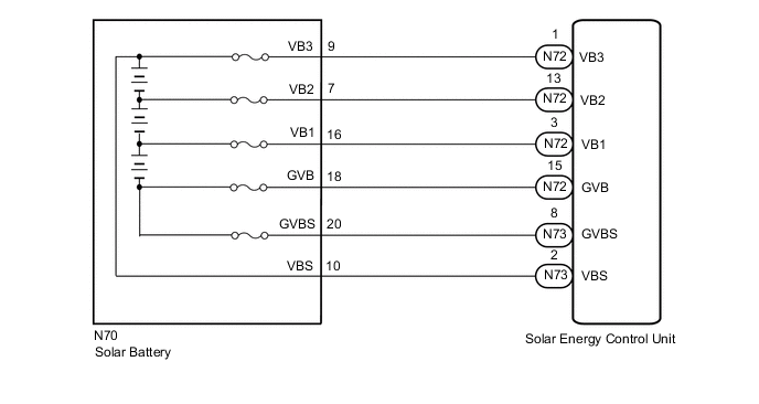
WIRING DIAGRAM
CAUTION / NOTICE / HINT
CAUTION:
-

Before performing any of the following operations, take precautions to prevent electric shock by turning the power switch off, wearing insulated gloves, and removing the service plug grip.
-
Inspecting the high-voltage system.
-
Disconnecting the low voltage connector of the inverter with converter assembly.
-
Disconnecting the low voltage connector of the HV battery.
-
Disconnecting the low voltage connector of the electric vehicle charger assembly.
-
Disconnecting the low voltage connector of the solar energy control unit.
-

To prevent electric shock, make sure to remove the service plug grip to cut off the high voltage circuit before servicing the vehicle.
-

After removing the service plug grip from the HV battery, put it in your pocket to prevent other technicians from accidentally reconnecting it while you are working on the high-voltage system.
-
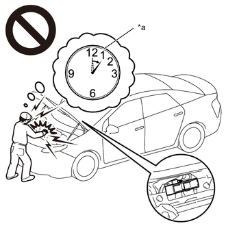
*a Without waiting for 10 minutes After removing the service plug grip, wait for at least 10 minutes before touching any of the high-voltage connectors or terminals. After waiting for 10 minutes, check the voltage at the terminals in the inspection point in the inverter with converter assembly. The voltage should be 0 V before beginning work.
Tech Tips
Waiting for at least 10 minutes is required to discharge the high-voltage capacitor inside the inverter with converter assembly.
Note
After turning the power switch off, waiting time may be required before disconnecting the cable from the negative (-) auxiliary battery terminal. Therefore, make sure to read the disconnecting the cable from the negative (-) auxiliary battery terminal notices before proceeding with work.
PROCEDURE
-
CHECK DTC OUTPUT (SOLAR CHARGING SYSTEM)
-
Connect the GTS to the DLC3.
-
Turn the power switch on (IG).
-
Enter the following menus: Powertrain / Solar Charging Control / Trouble Codes.
-
Check for DTCs.
Powertrain > Solar Charging Control > Trouble CodesResult Result Proceed to Only P1EC000, P1EC01E, P1EC200, P1EC21E, P1EC400 or P1EC41E only is output, or DTCs other than in the table below are also output. A Any of the DTCs in the table below are output. B Relevant DTC P1ECD16 Solar Charging Battery Control System Circuit Voltage Below Threshold P1ECF87 Lost Communication with Internal Control Module Solar Charger Battery Monitor Missing Message P1ED462 Solar Charging Battery Voltage Sensor Signal Compare Failure P1EDD13 Solar Charging Battery Voltage Sensor "A" Circuit Open P1EE213 Solar Charging Battery Voltage Sensor "B" Circuit Open P1EE713 Solar Charging Battery Voltage Sensor "C" Circuit Open -
Turn the power switch off.
B 
GO TO DTC CHART (SOLAR CHARGING SYSTEM) Click here
A 
-
-
CHECK SOLAR ENERGY CONTROL UNIT (CURRENT SENSOR)
CAUTION:
Be sure to wear insulated gloves.
Tech Tips
If the following procedure cannot be performed due to the condition of the vehicle, proceed to the next step.
-
Check that the service plug grip is not installed.
Note
After removing the service plug grip, do not turn the power switch on (READY), unless instructed by the repair manual because this may cause a malfunction.
-
Remove the rear seat cushion assembly LH.
-
Disconnect the solar energy control unit connectors and wait for 2 minutes or more.
Click here
Note
Before disconnecting the connectors, check that they are not loose or disconnected.
-
Reconnect the solar energy control unit connectors and wait for 5 minutes or more.
-
Connect the GTS to the DLC3.
-
Enter the following menus: Powertrain / Solar Charging Control / Data List / Solar Charge Hybrid Battery DC/DC Converter Input Power.
Powertrain > Solar Charging Control > Data ListTester Display Solar Charge Hybrid Battery DC/DC Converter Input Power -
Depress the brake pedal.
Tech Tips
The HV battery will begin charging.
If the SOC of the solar battery is low, the HV battery will not be charged.
If the SOC of the solar battery drops to 56%, shine a light on the solar panel to charge the solar battery for a while.
If the SOC of the HV battery is 91% or more, the HV battery will not be charged.
-
According to the display on the GTS, read the Data List and check that the value of "Solar Charge Hybrid Battery DC/DC Converter Input Power" is 50 W or more.
Tech Tips
Using this Data List item, charging of the HV battery can be confirmed.
-
Enter the following menus: Powertrain / Solar Charging Control / Data List.
Powertrain > Solar Charging Control > Data ListTester Display Solar Charging Battery Charging and Discharging Voltage Solar Charging Battery Current Solar Charge Auxiliary Battery DC/DC Converter Output Power Solar Charge Hybrid Battery DC/DC Converter Input Power Solar Charge Solar Charging Battery DC/DC Converter Output Power Note
Turning the power switch on (IG) with the service plug grip removed causes other DTCs to be stored. Clear the DTCs after performing this inspection.
-
According to the display on the GTS, read the Data List and record the value of "Solar Charging Control".
-
Use the following formula to calculate the judgment values.
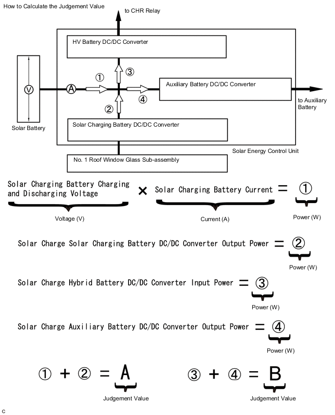
Specified Condition Result The difference between judgment value A and judgment value B is less than 60 W. Note
-
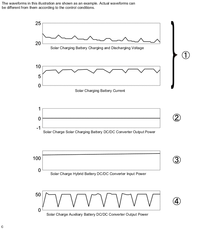
Measure the voltage (V), current (A) and power (W) while the HV battery is being charged.
-
Make sure not to perform measurements immediately after the HV battery begins charging or immediately before charging completes, as the values will fluctuate.
Tech Tips
The following illustration shows an example of the voltage (V), current (A) and power (W) while charging to the HV battery is being performed.
-
-
Install the rear seat cushion assembly LH.
Result Proceed to OK NG
NG
REPLACE SOLAR ENERGY CONTROL UNIT Click here
OK
-
-
CHECK HARNESS AND CONNECTOR (SOLAR ENERGY CONTROL UNIT - SOLAR BATTERY)
CAUTION:
Be sure to wear insulated gloves.
-
Check that the service plug grip is not installed.
Note
After removing the service plug grip, do not turn the power switch on (READY), unless instructed by the repair manual because this may cause a malfunction.
-
Remove the rear seat cushion assembly LH.
-
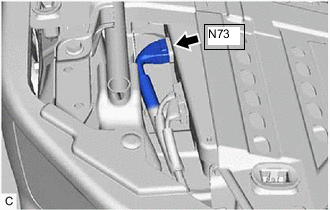
Disconnect the N73 solar energy control unit connector.
-
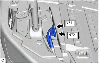
Disconnect the N71 and N72 solar energy control unit connectors.
-
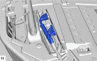
Remove the No. 1 solar battery shield panel.
-
Disconnect the N70 solar battery connector.
-
Measure the resistance according to the value(s) in the table below.
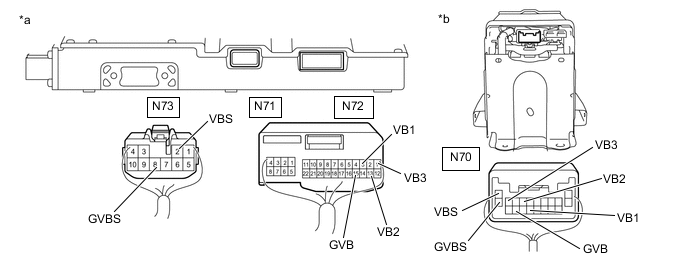
*a Rear view of wire harness connector
(to Solar Energy Control Unit)
*b Rear view of wire harness connector
(to Solar Battery)
Standard Resistance (Check for Open) Tester Connection Condition Specified Condition N72-1 (VB3) - N70-9 (VB3) Power switch off Below 1 Ω N72-13 (VB2) - N70-7 (VB2) Power switch off Below 1 Ω N72-3 (VB1) - N70-16 (VB1) Power switch off Below 1 Ω N72-15 (GVB) - N70-18 (GVB) Power switch off Below 1 Ω N73-8 (GVBS) - N70-20 (GVBS) Power switch off Below 1 Ω N73-2 (VBS) - N70-10 (VBS) Power switch off Below 1 Ω Standard Resistance (Check for Short) Tester Connection Condition Specified Condition N72-1 (VB3) or N70-9 (VB3) - Body ground and other terminals Power switch off 10 kΩ or higher N72-13 (VB2) or N70-7 (VB2) - Body ground and other terminals Power switch off 10 kΩ or higher N72-3 (VB1) or N70-16 (VB1) - Body ground and other terminals Power switch off 10 kΩ or higher N72-15 (GVB) or N70-18 (GVB) - Body ground and other terminals Power switch off 10 kΩ or higher N73-8 (GVBS) or N70-20 (GVBS) - Body ground and other terminals Power switch off 10 kΩ or higher N73-2 (VBS) or N70-10 (VBS) - Body ground and other terminals Power switch off 10 kΩ or higher -
Reconnect the N70 solar battery connector.
-
Install the No. 1 solar battery shield panel.
-
Reconnect the N71 and N72 solar energy control unit connectors.
-
Reconnect the N73 solar energy control unit connector.
-
Install the rear seat cushion assembly LH.
Result Proceed to OK NG
NG
REPAIR OR REPLACE HARNESS OR CONNECTOR
OK
-
-
CHECK SOLAR ENERGY CONTROL UNIT (VOLTAGE SENSOR)
CAUTION:
Be sure to wear insulated gloves.
-
Check that the service plug grip is not installed.
Note
After removing the service plug grip, do not turn the power switch on (READY), unless instructed by the repair manual because this may cause a malfunction.
-
Remove the rear seat cushion assembly LH.
-
Connect the GTS to the DLC3.
-
Turn the power switch on (IG).
-
Enter the following menus: Powertrain / Solar Charging Control / Data List.
Powertrain > Solar Charging Control > Data ListTester Display Solar Charging Battery Charging and Discharging Voltage Solar Charging Battery Block Total Voltage Solar Charging Battery Block 1 Voltage Solar Charging Battery Block 2 Voltage Solar Charging Battery Block 3 Voltage Solar Charging Battery Block 1 Voltage Sensor Upper Side Voltage Solar Charging Battery Block 1 Voltage Sensor Under Side Voltage Solar Charging Battery Block 2 Voltage Sensor Upper Side Voltage Solar Charging Battery Block 2 Voltage Sensor Middle Side Voltage Solar Charging Battery Block 2 Voltage Sensor Under Side Voltage Solar Charging Battery Block 3 Voltage Sensor Upper Side Voltage Solar Charging Battery Block 3 Voltage Sensor Under Side Voltage Note
-
Turning the power switch on (IG) with the service plug grip removed causes other DTCs to be stored. Clear the DTCs after performing this inspection.
-
If the power switch is turned on (IG) with the connectors disconnected, ]other DTCs will be stored. Be sure to clear the DTCs after the inspection.
-
-
According to the display on the GTS, read the Data List.
-
Turn the power switch off.
-
Disconnect the N71 and N72 solar energy control unit connectors.
-
Disconnect the N73 solar energy control unit connector.
-
Compare the Data List values with those shown in the following combination table.
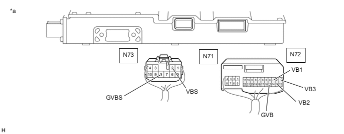
*a Rear view of wire harness connector
(to Solar Energy Control Unit)
- - Specified Condition Tester Connection Tester Display Specified Condition N72-3 (VB1) - N72-15 (GVB) Solar Charging Battery Block 1 Voltage Difference between the value in the Data List and the actual measured value at the solar energy control unit connector is 0.1 V or less. N72-13 (VB2) - N72-3 (VB1) Solar Charging Battery Block 2 Voltage Difference between the value in the Data List and the actual measured value at the solar energy control unit connector is 0.1 V or less. N72-1 (VB3) - N72-13 (VB2) Solar Charging Battery Block 3 Voltage Difference between the value in the Data List and the actual measured value at the solar energy control unit connector is 0.1 V or less. N73-8 (GVBS) - N73-2 (VBS) Solar Charging Battery Charging and Discharging Voltage Difference between the value in the Data List and the actual measured value at the solar energy control unit connector is 0.3 V or less. N72-15 (GVB) - N72-1 (VB3) Solar Charging Battery Block Total Voltage Difference between the value in the Data List and the actual measured value at the solar energy control unit connector is 0.3 V or less. Condition (All of the following conditions are met.) "Solar Charging Battery Block 1 Voltage Sensor Upper Side Voltage" - "Solar Charging Battery Block 1 Voltage Sensor Under Side Voltage" = 0.2 V or less "Solar Charging Battery Block 2 Voltage Sensor Upper Side Voltage" - "Solar Charging Battery Block 2 Voltage Sensor Middle Side Voltage" = 0.2 V or less "Solar Charging Battery Block 2 Voltage Sensor Middle Side Voltage" - "Solar Charging Battery Block 2 Voltage Sensor Under Side Voltage" = 0.2 V or less "Solar Charging Battery Block 2 Voltage Sensor Upper Side Voltage" - "Solar Charging Battery Block 2 Voltage Sensor Under Side Voltage" = 0.2 V or less "Solar Charging Battery Block 3 Voltage Sensor Upper Side Voltage" - "Solar Charging Battery Block 3 Voltage Sensor Under Side Voltage" = 0.2 V or less "Solar Charging Battery Charging and Discharging Voltage" - "Solar Charging Battery Block Total Voltage" = 0.2 V or less -
Reconnect the N71 and N72 solar energy control unit connectors.
-
Reconnect the N73 solar energy control unit connector.
-
Install the rear seat cushion assembly LH.
Result Proceed to OK NG
OK
REPLACE SOLAR BATTERY Click here
NG
REPLACE SOLAR ENERGY CONTROL UNIT Click here
-