SOLAR CHARGING SYSTEM TERMINALS OF ECU
-
SOLAR ENERGY CONTROL UNIT
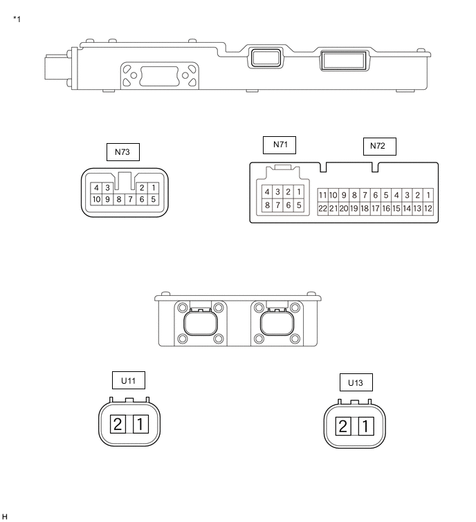
*1 Solar Energy Control Unit - - Solar Energy Control Unit Terminal No.
(Symbol)
Wiring Color Input/Output Terminal Description Condition Specified Condition N71-1 (IGCT) - N73-9 (E01) G - W-B IN IGCT signal Power switch on (IG) 11 to 14 V N71-3 (CA1L) - N73-9 (E01) W - W-B IN/OUT CAN Communication signal Power switch on (IG) Pulse generation
(Waveform 1)
N71-4 (CA4H) - N73-9 (E01) GR - W-B IN/OUT CAN Communication signal Power switch on (IG) Pulse generation
(Waveform 2)
N71-5 (ACC) - N73-9 (E01) R - W-B IN ACC signal Power switch on (ACC) 11 to 14 V N71-7 (CA1H) - N73-9 (E01) V - W-B IN/OUT CAN Communication signal Power switch on (IG) Pulse generation
(Waveform 1)
N71-8 (CA4L) - N73-9 (E01) W - W-B IN/OUT CAN Communication signal Power switch on (IG) Pulse generation
(Waveform 2)
N72-1 (VB3) - N72-13 (VB2) LG - SB IN Solar battery block voltage Always 6 to 10 V N72-3 (VB1) - N72-15 (GVB) GR - B IN Solar battery block voltage Always 6 to 10 V N72-5 (TB0) - N72-17 (GB0) W - LG IN Solar charging battery temperature sensor 1 Power switch on (IG)
Solar battery temperature: -30 to 60°C (-22 to 140°F)
2.8 V (-30°C (-22°F)) to 0.6 V (60°C (140°F)) N72-7 (TB1) - N72-19 (GB1) R - G IN Solar charging battery temperature sensor 2 Power switch on (IG)
Solar battery temperature: -30 to 60°C (-22 to 140°F)
2.8 V (-30°C (-22°F)) to 0.6 V (60°C (140°F)) N72-9 (TB2) - N72-21 (GB2) L - P IN Solar charging battery temperature sensor 3 Power switch on (IG)
Solar battery temperature: -30 to 60°C (-22 to 140°F)
2.8 V (-30°C (-22°F)) to 0.6 V (60°C (140°F)) N72-11 (SSEN) - N73-9 (E01) G - W-B IN HV battery charging permission signal HV battery DC/DC converter operation permitted 2.0 to 14.5 V HV battery DC/DC converter operation prohibited Below 2 V N72-13 (VB2) - N72-3 (VB1) SB - GR IN Solar battery block voltage Always 6 to 10 V N73-2 (VBS) - N73-8 (GVBS) GR - G IN/OUT Solar battery voltage Always 18 to 30 V N73-4 (AMD) - N73-9 (E01) P - W-B IN/OUT Auxiliary battery voltage Always Same as auxiliary battery voltage N73-5 (VSOP) - N73-7 (VSON) B - L IN Solar panel voltage Varies with amount of solar radiation 0 to 55 V
-
Oscilloscope waveforms
Tech Tips
Oscilloscope waveform samples are provided here for informational purposes. Noise and fluttering waveforms have been omitted.
-
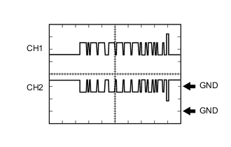
Waveform 1 (CAN communication signal)
Item Content Terminal CH1: N71-7 (CA1H) - N73-9 (E01)
CH2: N71-3 (CA1L) - N73-9 (E01)
Equipment Setting 1 V/DIV., 50 μs./DIV. Condition Power switch on (IG) Tech Tips
The waveform will vary depending on the content of the digital communication (digital signal).
-

Waveform 3 (CAN communication signal)
Item Content Terminal CH1: N71-4 (CA4H) - N73-9 (E01)
CH2: N71-8 (CA4L) - N73-9 (E01)
Equipment Setting 1 V/DIV., 50 μs./DIV. Condition Power switch on (IG) Tech Tips
The waveform will vary depending on the content of the digital communication (digital signal).
-
-