BLIND SPOT MONITOR SENSOR REMOVAL

CAUTION / NOTICE / HINT
The necessary procedures (adjustment, calibration, initialization, or registration) that must be performed after parts are removed and installed, or replaced during blind spot monitor sensor removal/installation are shown below.
| Replaced Part or Performed Procedure | Necessary Procedure | Effect/Inoperative Function when Necessary Procedure not Performed | Link |
|---|---|---|---|
| Blind spot monitor sensor | Blind spot monitor beam axis adjustment | DTCs are output | |
| Rear bumper assembly (w/ Intelligent clearance sonar system) |
|
|
PROCEDURE
-
REMOVE REAR BUMPER ASSEMBLY
-
REMOVE BLIND SPOT MONITOR SENSOR LH
-
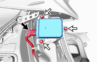
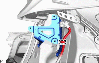
Disconnect the connector.
-
Remove the 3 nuts and blind spot monitor sensor LH.
Note
Replace the blind spot monitor sensor if it has been dropped or subjected to a severe impact.
-
-
REMOVE BLIND SPOT MONITOR SENSOR RH
-
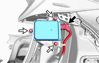
Disconnect the connector.
-
Remove the 3 nuts and blind spot monitor sensor RH.
Note
Replace the blind spot monitor sensor if it has been dropped or subjected to a severe impact.
-
-
REMOVE BLIND SPOT MONITOR BRACKET LH
-
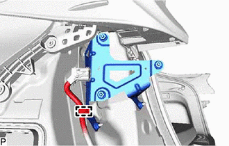
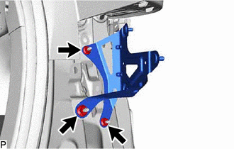
Disengage the clamp.
-
Remove the 3 nuts and blind spot monitor bracket LH.
-
-
REMOVE BLIND SPOT MONITOR BRACKET RH
-
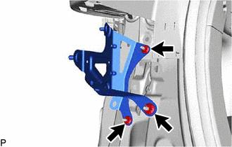
Disengage the clamp.
-
Remove the 3 nuts and blind spot monitor bracket RH.
-