TOYOTA PARKING ASSIST-SENSOR SYSTEM TERMINALS OF ECU
-
CLEARANCE WARNING ECU ASSEMBLY

-
Disconnect the I28 clearance warning ECU assembly connector.
-
Measure the voltage and resistance on the wire harness side connector according to the value(s) in the table below.
Terminal No. (Symbol) Wiring Color Terminal Description Condition Specified Condition I28-1 (IG) - I28-30 (E) L - W-B IG power source signal Power switch off Below 1 V Power switch on (IG) 11 to 14 V I28-30 (E) - Body ground W-B - Body ground Ground Always Below 1 Ω -
Reconnect the I28 clearance warning ECU assembly connector.
-
Measure the voltage and check for pulses according to the value(s) in the table below.
Terminal No. (Symbol) Wiring Color Terminal Description Condition Specified Condition I28-2 (CSB1) - I28-30 (E) V - W-B Power source for front side sensor circuit Power switch off Below 1 V
-
Power switch on (IG)
-
TOYOTA parking assist-sensor system on
11 to 14 V I28-4 (BOF) - I28-30 (E) BE - W-B Power source for front sensor circuit Power switch off Below 1 V
-
Power switch on (IG)
-
TOYOTA parking assist-sensor system on
11 to 14 V I28-5 (CSG1) - I28-30 (E) V - W-B Ground for front side clearance sonar Always Below 1 V I28-6 (E5) - I28-30 (E) GR - W-B Ground for front clearance sonar Always Below 1 V I28-7 (LIN1) - I28-30 (E) B - W-B Front side sensor communication signal (Front side clearance sonar sensor)
-
Power switch on (READY)
-
TOYOTA parking assist-sensor system on
-
Other than park (P) has been selected
-
Vehicle speed is less than approximately 10 km/h (6 mph)
Pulse generation
(Refer to waveform 4)
I28-8 (SOF) - I28-30 (E) G - W-B Front sensor communication signal (Front clearance sonar sensor)
-
Power switch on (READY)
-
TOYOTA parking assist-sensor system on
-
Reverse (R) has been selected
-
Vehicle speed is less than approximately 10 km/h (6 mph)
Pulse generation
(Refer to waveform 1)
I28-13 (EF) - I28-30 (E) P - W-B Ground for clearance warning buzzer Always Below 1 V I28-14 (CBZ) - I28-13 (EF) SB - P Clearance warning buzzer signal Buzzer sounding Pulse generation
(Refer to waveform 2)
I28-15 (BBZ) - I28-16 (ER) L - B Clearance warning buzzer signal Buzzer sounding Pulse generation
(Refer to waveform 3)
I28-16 (ER) - I28-30 (E) B - W-B Ground for clearance warning buzzer Always Below 1 V I28-21 (CSB2) - I28-30 (E) L - W-B Power source for rear side sensor circuit Power switch off Below 1 V
-
Power switch on (IG)
-
TOYOTA parking assist-sensor system on
11 to 14 V I28-22 (BOR) - I28-30 (E) LG - W-B Power source for rear sensor circuit Power switch off Below 1 V
-
Power switch on (IG)
-
TOYOTA parking assist-sensor system on
11 to 14 V I28-23 (E1) - I28-30 (E) SB - W-B Ground for rear clearance sonar Always Below 1 V I28-24 (SOR) - I28-30 (E) P - W-B Rear sensor communication signal (Rear clearance sonar sensor)
-
Power switch on (READY)
-
TOYOTA parking assist-sensor system on
-
Reverse (R) has been selected
-
Vehicle speed is less than approximately 10 km/h (6 mph)
Pulse generation
(Refer to waveform 1)
I28-25 (CSG2) - I28-30 (E) BE - W-B Ground for rear side clearance sonar Always Below 1 V I28-26 (LIN2) - I28-30 (E) R - W-B Rear side sensor communication signal (Rear side clearance sonar sensor)
-
Power switch on (READY)
-
TOYOTA parking assist-sensor system on
-
Other than park (P) has been selected
-
Vehicle speed is less than approximately 10 km/h (6 mph)
Pulse generation
(Refer to waveform 4)
-
-
Using an oscilloscope, check waveform 1.
-
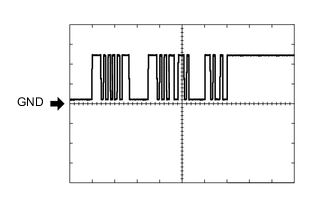
Waveform 1 (Reference)
Item Content Measurement terminal
-
I28-8 (SOF) - I28-30 (E)
-
I28-24 (SOR) - I28-30 (E)
Measurement setting 5 V/DIV., 1 ms./DIV. Condition
-
Power switch on (READY)
-
TOYOTA parking assist-sensor system on
-
Reverse (R) has been selected
-
Vehicle speed is less than approximately 10 km/h (6 mph)
-
-
-
Using an oscilloscope, check waveform 2.
-
Waveform 2 (Reference)
Item Content Measurement terminal I28-14 (CBZ) - I28-13 (EF) Measurement setting 2 V/DIV., 500 μs./DIV. Condition Buzzer sounding Tech Tips
The amplitude of the waveform changes according to the set volume.
-
-
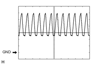
Using an oscilloscope, check waveform 3.
-
Waveform 3 (Reference)
Item Content Measurement terminal I28-15 (BBZ) - I28-16 (ER) Measurement setting 2 V/DIV., 1000 μs./DIV. Condition Buzzer sounding Tech Tips
The amplitude of the waveform changes according to the set volume.
-
-
Using an oscilloscope, check waveform 4.
-
Waveform 4 (Reference)
Item Content Measurement terminal
-
I28-7 (LIN1) - I28-30 (E)
-
I28-26 (LIN2) - I28-30 (E)
Measurement setting 5 V/DIV., 1 ms./DIV. Condition
-
Power switch on (READY)
-
TOYOTA parking assist-sensor system on
-
Other than park (P) has been selected
-
Vehicle speed is less than approximately 10 km/h (6 mph)
-
-
-