NAVIGATION SYSTEM(for Navigation Receiver Type) Reverse Signal Circuit
DESCRIPTION
The navigation receiver assembly receives a reverse signal from the BKUP LP relay.
WIRING DIAGRAM
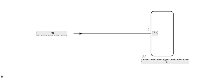
| *a | from BKUP LP Relay |
| *b | REV |
| *c | Navigation Receiver Assembly |
PROCEDURE
-
CHECK BACK-UP LIGHT
-
Check that the back-up light comes on.
OK The back-up light comes on. Result Proceed to OK NG
NG 
GO TO LIGHTING SYSTEM Click here
OK 
-
-
CHECK HARNESS AND CONNECTOR (REVERSE SIGNAL)
-
Disconnect the I33 navigation receiver assembly connector.
-
Measure the voltage according to the value(s) in the table below.
Standard Voltage Tester Connection Condition Specified Condition I33-2 (REV) - Body ground Power switch on (IG)
Reverse (R) selected
11 to 14 V I33-2 (REV) - Body ground Power switch on (IG)
Shift state other than reverse (R) selected
Below 1 V Result Proceed to OK NG
OK
PROCEED TO NEXT SUSPECTED AREA SHOWN IN PROBLEM SYMPTOMS TABLE Click here
NG
REPAIR OR REPLACE HARNESS OR CONNECTOR
-