NAVIGATION SYSTEM(for Radio and Display Type) OPERATION CHECK
-
CHECK NAVIGATION SYSTEM NORMAL CONDITION
-
If the symptom is applicable to any of the following, it is intended behavior, and not a malfunction.
Symptom Answer A longer route than expected is chosen. Depending on the road conditions, the navigation ECU may determine that a longer route is quicker. Even when distance priority is high, the shortest route is not shown. Some routes may not be advised due to safety concerns. When the vehicle is put into motion immediately after the engine starts, the navigation system deviates from the correct position. If the vehicle starts before the navigation system activates, the system may not react. When driving on certain types of roads, especially new roads, the vehicle position deviates from the correct position. When the vehicle is driving on new roads not available on the internal memory, the system attempts to match it to another nearby road, causing the position mark to deviate. Expected arrival time is earlier than current time, or time different from expected arrival time is displayed. If a destination is set to a point where a different time zone is used, the system displays an expected arrival time corresponding to the time zone of the destination. If a location on the sea is set as the destination, the system may display an expected arrival time corresponding to the time zone setting of the vehicle. Check which communication is not used for displaying traffic information. -
The following symptoms are not malfunctions, but are caused by errors inherent in the GPS, gyro sensor or navigation ECU.
-
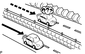
The current position mark may be displayed on a nearby parallel road.
-
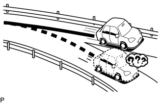
Immediately after a fork in the road, the current vehicle position mark may be displayed on the wrong road.
-
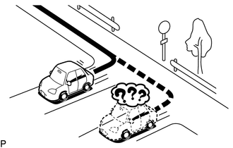
When the vehicle turns right or left at an intersection, the current vehicle position mark may be displayed on a nearby parallel road.
-
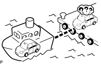
When the vehicle is carried, such as on a ferry, and the vehicle itself is not driving, the current vehicle position mark may be displayed in the position where the vehicle was until a measurement can be performed by the GPS.
-
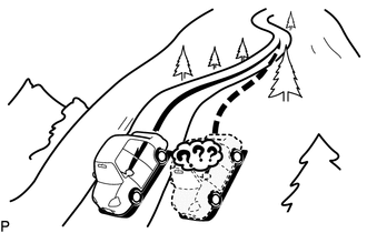
When the vehicle travels on a steep hill, the current vehicle position mark may deviate from the correct position.
-
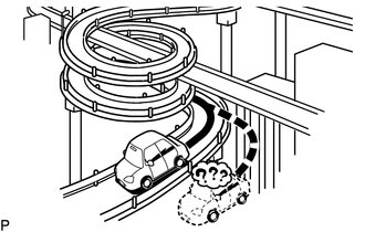
When the vehicle makes a continuous turn (e.g. 360, 720, 1080 degrees), the current vehicle position mark may deviate from the correct position.
-
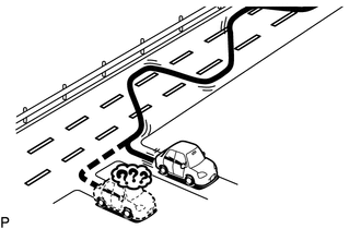
When the vehicle moves erratically, such as constant lane changes, the current vehicle position mark may deviate from the correct position.
-
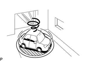
When the power switch is turned on (ACC) or on (IG) and the vehicle is turned on a turntable before parking, the current vehicle position mark may not indicate the correct direction. The same will occur when the vehicle comes out of the parking garage.
-
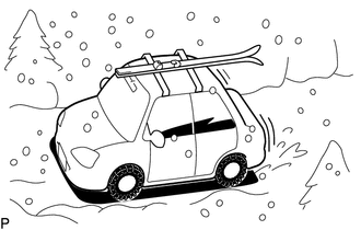
When the vehicle travels on a snowy road or a mountain path with tire chains installed or using a spare tire, the current vehicle position mark may deviate from the correct position.
-
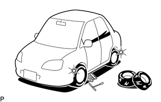
When the tires are changed, the current vehicle position mark may deviate from the correct position.
Tech Tips
-
A change in tire diameter may cause a speed sensor error.
-
Performing "tire change" in calibration mode will allow the system to correct the current vehicle position faster.
-
-
-
-
CHECK PANEL & STEERING SWITCH
Tech Tips
-
The radio and display receiver assembly panel switches and steering switches are checked in the following procedure.
-
Illustrations may differ from the actual vehicle screen depending on the device settings and options. Therefore, some detailed areas may not be shown exactly the same as on the actual vehicle screen.
-
Enter diagnostic mode.
-
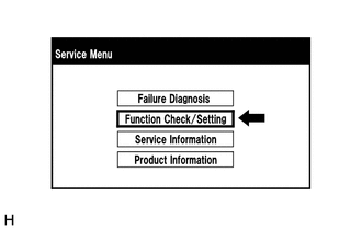
Select "Function Check/Setting" from the "Service Menu" screen.
-
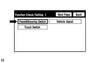
Select "Panel & Steering Switch" from the "Function Check/Setting I" screen.
-
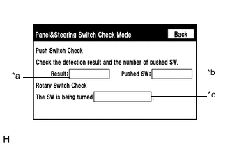
Panel & Steering Switch Check Mode
Screen Description Display Content *a: Switch condition "Pushed" is displayed when any switch is pushed. *b: Number of switches pushed
-
Number of switches pushed at once is displayed.
-
If more than 3 switches are pushed at once, "More than 3" is displayed.
-
If 4 or more switches are pushed at once, "More than 3" is displayed
*c: Rotary switch direction Direction of rotary switch is displayed.
-
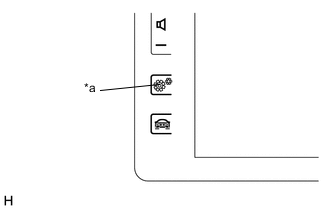
*a Setup Switch Operate each switch and check that the switch conditions are correctly displayed.
Tech Tips
If the setup switch is pressed and held for 3 seconds or more, diagnostic mode will be canceled.
-
-
-
CHECK TOUCH SWITCH
Tech Tips
-
The touch switches on the screen are checked in the following procedure.
-
Illustrations may differ from the actual vehicle screen depending on the device settings and options. Therefore, some detailed areas may not be shown exactly the same as on the actual vehicle screen.
-
Enter diagnostic mode.
-
Select "Function Check/Setting" from the "Service Menu" screen.
-
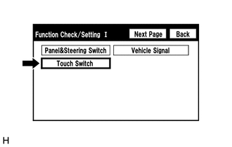
Select "Touch Switch" from the "Function Check/Setting I" screen.
-
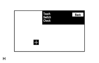
Touch Switch Check
-
Touch the display anywhere in the open area to perform the check when the "Touch Switch Check" screen is displayed.
Tech Tips
-
A "+" mark is displayed where the display was touched.
-
The "+" mark remains on the display even after your finger is removed.
-
-
-
-
CHECK VEHICLE SIGNAL
Tech Tips
-
Vehicle signals received by the radio and display receiver assembly are checked in the following procedure.
-
Illustrations may differ from the actual vehicle screen depending on the device settings and options. Therefore, some detailed areas may not be shown exactly the same as on the actual vehicle screen.
-
Enter diagnostic mode.
-
Select "Function Check/Setting" from the "Service Menu" screen.
-
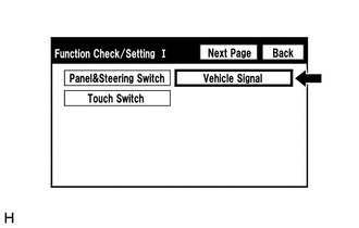
Select "Vehicle Signal" from the "Function Check/Setting I" screen.
-
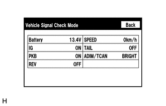
Vehicle Signal Check Mode
Screen Description Display Content Battery Auxiliary battery voltage is displayed. IG Power switch ON/OFF state is displayed. PKB Parking brake ON/OFF state is displayed. REV Reverse signal ON/OFF state is displayed. SPEED Vehicle speed is displayed in km/h. TAIL Tail signal (light control switch) ON/OFF state is displayed. ADIM/TCAN Brightness state DIM (with)/BRIGHT (without) is displayed. Tech Tips
-
Only items sending vehicle signals will be displayed.
-
This screen displays vehicle signals input to the radio and display receiver assembly.
-
This screen is updated once per second.
-
When the "Vehicle Signal Check Mode" screen is displayed, check all the vehicle signal conditions.
-
-
-
CHECK DAB RECEPTION
Tech Tips
-
The reception condition of DAB (Digital Audio Broadcast) can be checked.
-
Illustrations may differ from the actual vehicle screen depending on the device settings and options. Therefore, some detailed areas may not be shown exactly the same as on the actual vehicle screen.
-
Enter diagnostic mode.
-
Select "Function Check/Setting" from the "Service Menu" screen.
-
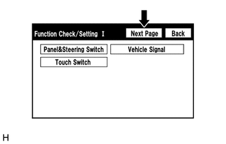
Select "Next Page" from the "Function Check/Setting I" screen.
-
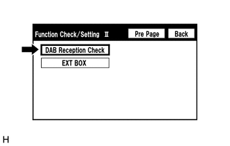
Select "DAB Reception Check" from the "Function Check/Setting II" screen.
-
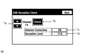
DAB Reception Check
*a: Channel Change Switch Description Display Content Up or down button Enables the channel to be changed to the one to be checked. *b: Check Switch Description Display Condition Content Check Before/after check Starts checking STOP During check Stops checking *c: Antenna Connection Check Result Description Display Content OK Connected properly NG Not connected properly - Not equipped with DAB antenna *d: DAB Tuner Reception Level Check Result Description Display Content Black Good reception Red Poor reception - Not equipped with DAB antenna
-
Select "Check" to start the DAB reception check.
-
Check the results displayed when the DAB reception check is complete.
-
-
-
CHECK MICROPHONE
Tech Tips
-
The microphone and microphone input level are checked in the following procedure.
-
Illustrations may differ from the actual vehicle screen depending on the device settings and options. Therefore, some detailed areas may not be shown exactly the same as on the actual vehicle screen.
-
Enter diagnostic mode.
-
Select "Function Check/Setting" from the "Service Menu" screen.
-
Select "Next Page" from the "Function Check/Setting I" screen.
-
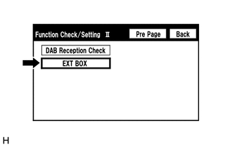
Select "EXT BOX" from the "Function Check/Setting II" screen.
-
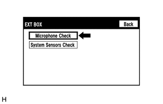
Select "Microphone Check" from the "EXT BOX" screen.
-
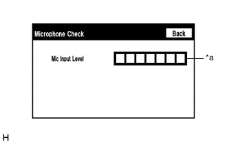
Microphone Check
Screen Description Display Content *a: Microphone input level meter Monitors the microphone input level every 0.1 seconds and displays the results in 8 different levels.
-
When speaking into the microphone, check that the microphone input level meter changes according to the input level.
Tech Tips
The microphone is active at all times when this screen is displayed.
-
-
-
CHECK SYSTEM SENSORS
Tech Tips
-
GPS information, vehicle signals and sensor signals are checked in the following procedure.
-
Illustrations may differ from the actual vehicle screen depending on the device settings and options. Therefore, some detailed areas may not be shown exactly the same as on the actual vehicle screen.
-
Enter diagnostic mode.
-
Select "Function Check/Setting" from the "Service Menu" screen.
-
Select "Next Page" from the "Function Check/Setting I" screen.
-
Select "EXT BOX" from the "Function Check/Setting II" screen.
-
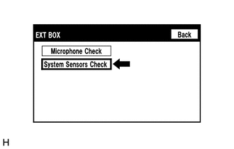
Select "System Sensors Check" from the "EXT BOX" screen.
-
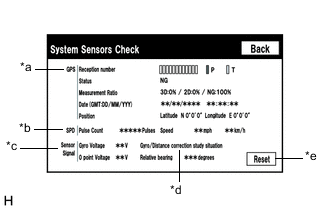
System Sensors Check
*a: GPS Display Content Reception number Displays reception condition of the satellites used to determine vehicle position Blue: P (In use) System is using GPS signal for location Yellow: T (Receiving) System is tracking GPS signal for location No color: Not in use System cannot receive GPS signal (searching for GPS signal) Status Displays reception status of the satellites used to determine vehicle position OK (H3D) High accuracy 3-dimensional location method is being used OK (H2D) High accuracy 2-dimensional location method is being used OK (3D) 3-dimensional location method is being used OK (2D) 2-dimensional location method is being used NG Location data cannot be used error Reception error has occurred - Any other state Measurement Ratio Displays the ratio of satellites performing measurements 3D Ratio of satellites performing 3D positioning, Hyper 3D positioning and Hyper 2D positioning is displayed 2D Ratio of satellites performing 2D positioning is displayed NG Ratio of satellites not performing measurement is displayed Date Date/time information obtained from GPS signals is displayed in Greenwich Mean Time (GMT) Position Latitude and longitude information on current position is displayed *b: SPD Display Content Pulse Count Displays the accumulated number of input pulses beginning when this screen is displayed Speed Displays vehicle speed *c: Sensor Signal Display Content Note Gyro Voltage Displays the output voltage of the gyro sensor - 0 point Voltage Displays the zero-point voltage of the gyro sensor - Relative bearing Displays the output angle of the gyro sensor The amount of change in bearing angle (degrees) after the system sensor check screen is displayed (clockwise: "+", counterclockwise: "-") *d: Gyro/Distance correction study situation Display Content Gyro/Distance correction study situation Displays learning status of Gyro/Distance correction *e: Reset Display Content Reset When this switch is pressed and held for 3 seconds or more, the values for the display items of SPD and Sensor Signal are reset and display "0"
-
When the "System Sensors Check" screen is displayed, check all the sensor signals.
Tech Tips
This screen is updated once per second.
-
-
-
CHECK SPEAKER
Tech Tips
-
This function is used when checking the speaker wiring and whether the speakers are functioning properly.
-
Illustrations may differ from the actual vehicle screen depending on the device settings and options. Therefore, some detailed areas may not be shown exactly the same as on the actual vehicle screen.
-
Turn audio mode on and play any audio source.
Tech Tips
This audio source will be used for the speaker check.
-
Enter diagnostic mode.
-
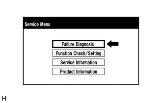
Select "Failure Diagnosis" from the "Service Menu" screen.
-
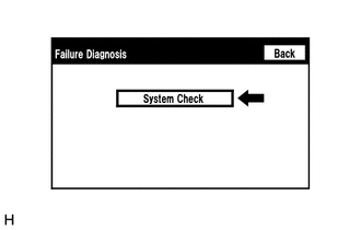
Select "System Check" from the "Failure Diagnosis" screen.
-
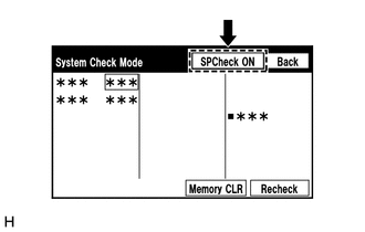
Select "SP Check ON" from the "System Check Mode" screen.
-
Check the speaker wiring and check that the speakers are functioning properly.
Tech Tips
-
Check that each speaker outputs sound from the selected audio source properly.
-
"SP Check OFF" is displayed during the speaker check.
-
Sound can be heard from the speakers around the vehicle in order beginning from a speaker on the front side.
-
More than one speaker may sound simultaneously depending on the speaker wiring.
-
-
Sound stops when any of the following conditions are met:
-
"SP Check OFF" is selected.
-
The power switch is turned off.
-
Diagnostic mode is turned off.
-
The screen is changed to another screen.
-
Audio mode is turned off.
-
-
-
CHECK SOFTWARE ERROR HISTORY
Tech Tips
This function is used to check the cause when the radio and display receiver assembly screen is blacked out.
-
Check Software Error History.
-
Connect the GTS to the DLC3.
-
Turn the power switch on (IG).
-
Turn the GTS on.
-
Enter the following menus: Body Electrical / Navigation System / Utility / Software Error History.
Body Electrical > Navigation System > UtilityTester Display Software Error History -
When an item is stored for Software Error History, record it before repairing the radio and display receiver assembly.
Software Error History Screen Description Error Description Trigger Detail Software Reset Navi Microcomputer Hexadecimal Number Audio Microcomputer CAN Microcomputer No Video Signal Front Monitor Rear Monitor MOST Cold Restart Always Tech Tips
-
Software Error History can store up to 5 history data items. If a new software error occurs when 5 data items have already been stored, the oldest data is cleared and the new data is stored.
-
If an error that is unsupported by the GTS occurs, a "-" is displayed for the display items.
-
-
-
Clear software error history.
-
When DTCs are cleared using any of the following operations, Software Error History will be cleared as well.
-
Cleared using the GTS.
-
Cleared using the system check mode screen.
-
Cleared using the unit check mode screen.
-
-
-
-
CHECK VIDEO DEVICE CONNECTION CHECK
Tech Tips
This function is used to detect disconnection of the video devices.
-
Check Video Device Connection Check.
-
Connect the GTS to the DLC3.
-
Turn the power switch on (IG).
-
Turn the GTS on.
-
Enter the following menus: Body Electrical / Navigation System / Utility / Video Device Connection Check.
Body Electrical > Navigation System > UtilityTester Display Video Device Connection Check -
When an item is stored for Video Device Connection Check, record it before proceeding with troubleshooting.
Tech Tips
-
DTCs are stored when errors are detected.
-
Depending on the vehicle, some of the items are not displayed on the "Error Detected Image Line (Type)" screen.
Video Device Connection Check Screen Description Error Detected Image Line (Type) Areas to be Checked H/U - > Separate Display (GVIF) Not available H/U - > Full RSE (GVIF) Not available RSE - > Seat Back Display RH (GVIF) Not available RSE - > Seat Back Display LH (GVIF) Not available Rear Camera - > H/U (NTSC) NTSC video signal between the radio and display receiver assembly and rear television camera assembly IPA/BGM/PVM ECU - > Separate Display (GVIF) Not available IPA/BGM/PVM ECU - > H/U (NTSC) Not available IPA/BGM/PVM ECU - > H/U (GVIF) Not available -
-
-
Clear video device connection check.
-
When DTCs are cleared using any of the following operations, Video Device Connection Check will be cleared as well.
-
Cleared using the GTS.
-
Cleared using the system check mode screen.
-
Cleared using the unit check mode screen.
-
-
-
-
CHECK Wi-Fi CONNECTION HISTORY (w/ "Wi-Fi" Function)
Tech Tips
This function is used to check the connection history when the connection between the radio and display receiver assembly and a Wi-Fi device is unstable.
-
Check Wi-Fi Connection History.
-
Connect the GTS to the DLC3.
-
Turn the power switch on (IG).
-
Turn the GTS on.
-
Enter the following menus: Body Electrical / Navigation System / Utility / Wi-Fi Connection History.
Body Electrical > Navigation System > UtilityTester Display Wi-Fi Connection History -
When a value for an item is displayed in Wi-Fi Connection History, record it before proceeding with troubleshooting.
Wi-Fi Connection History Screen Description Item Content Occurrence Date/Time Year is displayed in 4 digits and month, date, hour, minute and second are displayed in 2 digits Result Connect/Disconnect Success Timeout Communication Error Authentication Failure Disconnection Failure Other Failure Contents No Error AP Connection Error AP Connection Error (WPS) DHCP Connection Error DNS Connection Error HTTP Connection Error Other Error Destination MAC Address Displayed in lower case hexadecimal format with "-" inserted every two characters. Destination SSID Data is displayed as ASCII code WLAN Standard 802.11 b 802.11 g 802.11 n Undetectability Received Signal Strength -127 dBm to +127 dBm Data Rate 1.0 Mbps 2.0 Mbps 5.5 Mbps 6.0 Mbps 6.5 Mbps 9.0 Mbps 11.0 Mbps 12.0 Mbps 13.0 Mbps 18.0 Mbps 19.5 Mbps 24.0 Mbps 26.0 Mbps 36.0 Mbps 39.0 Mbps 48.0 Mbps 52.0 Mbps 54.0 Mbps 58.5 Mbps 65.0 Mbps Undetectability Packet Error Rate Displayed in decimal format with "%" Tech Tips
If there is no history for an item, "-" or "No Information" will be displayed.
-
-
Clear "Wi-Fi" connection history.
-
When DTCs are cleared using any of the following methods, Wi-Fi Connection History will be cleared as well.
-
Cleared using the GTS.
-
Cleared using the system check mode screen.
-
Cleared using the unit check mode screen.
-
-
-