RADIO ANTENNA CORD REMOVAL
CAUTION / NOTICE / HINT
The necessary procedures (adjustment, calibration, initialization, or registration) that must be performed after parts are removed and installed, or replaced during antenna cord sub-assembly removal/installation are shown below.
| Replaced Part or Performed Procedure | Necessary Procedure | Effect/Inoperative Function when Necessary Procedure not Performed | Link |
|---|---|---|---|
| Disconnect cable from negative auxiliary battery terminal | Memorize steering angle neutral point | Lane departure alert system (w/ Steering Control) | |
| Intelligent clearance sonar system*1 | |||
| Simple intelligent parking assist system*1 | |||
| Pre-crash safety system | |||
| Adaptive high beam system | |||
| Parking assist monitor system | |||
| Initialize back door lock | Power door lock control system |
*1: When performing learning using the GTS.
CAUTION:
Some of these service operations affect the SRS airbag system. Read the precautionary notices concerning the SRS airbag system before servicing.
PROCEDURE
-
REMOVE LOWER INSTRUMENT PANEL SUB-ASSEMBLY
-
REMOVE NO. 1 HEATER TO REGISTER DUCT SUB-ASSEMBLY (for RHD)
-
REMOVE NO. 2 HEATER TO REGISTER DUCT SUB-ASSEMBLY
-
REMOVE NO. 2 KNEE PROTECTOR BRACKET (for LHD)
-
REMOVE NO. 3 KNEE PROTECTOR BRACKET (for LHD)
-
REMOVE ANTENNA CORD SUB-ASSEMBLY
-
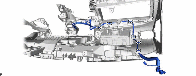
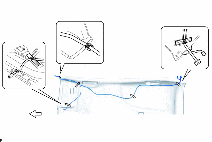
for LHD:
-
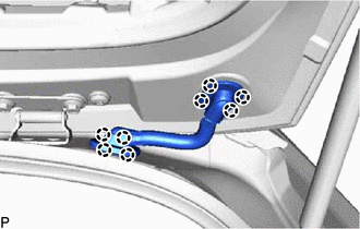
Disengage the 6 clamps and remove the antenna cord sub-assembly.
-
-
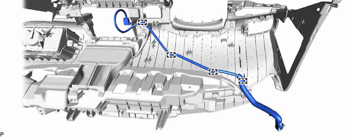
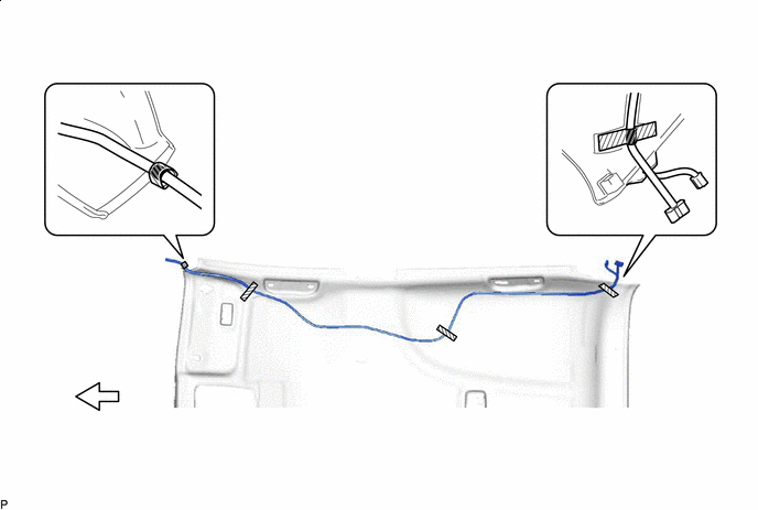
for RHD:
-
Disengage the 4 clamps and remove the antenna cord sub-assembly.
-
-
-
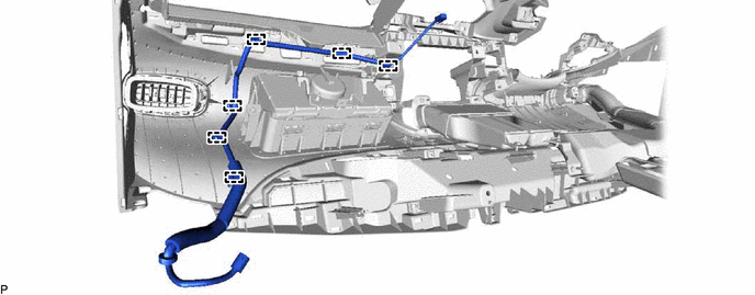
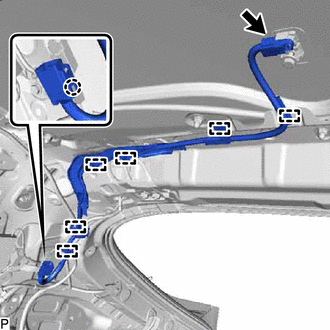
REMOVE ANTENNA CORD SUB-ASSEMBLY (for RHD)
-
w/ Navigation Antenna:
-
Disengage the 6 clamps and remove the antenna cord sub-assembly.
-
-
-
REMOVE ROOF HEADLINING ASSEMBLY
-
REMOVE NO. 2 ANTENNA CORD SUB-ASSEMBLY
-
w/o Digital Audio Broadcasting Antenna:
-
Remove the adhesive tape from the roof headlining assembly.

Adhesive Tape 
Front
-
-
w/ Digital Audio Broadcasting Antenna:
-
Disengage the clamp.
Adhesive Tape Front -
Remove the adhesive tape from the roof headlining assembly.
-
-
Remove the No. 2 antenna cord sub-assembly from the roof headlining assembly.
-
-
REMOVE NO. 5 ANTENNA CORD SUB-ASSEMBLY (w/ Digital Audio Broadcasting Antenna)
-
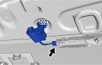
Disconnect the connector.
-
Disengage the clamp and remove the No. 5 antenna cord sub-assembly.
-
-
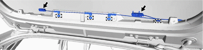
REMOVE NO. 3 ANTENNA CORD SUB-ASSEMBLY
-
Disconnect the connector.
-
Disengage the claw.
-
Disengage the 6 clamps and remove the No. 3 antenna cord sub-assembly.
-
-
REMOVE BACK DOOR UPPER TRIM PANEL ASSEMBLY
-
REMOVE NO. 4 ANTENNA CORD SUB-ASSEMBLY
-
w/o Glass Breakage Sensor:
-
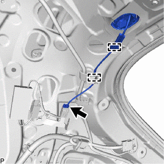
Disconnect the connector.
-
Disengage the 2 clamps.
-
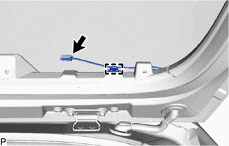
Disconnect the connector.
-
Disengage the clamp.
-
-
w/ Glass Breakage Sensor:
-
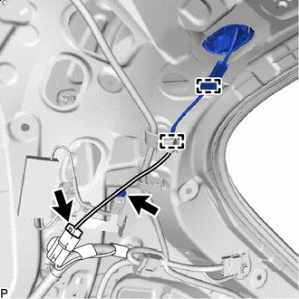
Disconnect the 2 connectors.
-
Disengage the 2 clamps.
-
Disconnect the 2 connectors.
-
Disengage the 4 clamps.
-
-
Disengage the 8 claws to separate the 2 grommets.
Note
When reusing the No. 4 antenna cord sub-assembly, make sure to replace the No. 1 wire harness protector and No. 2 wire harness protector with new ones as reusing them may cause water ingress.
-
Remove the No. 4 antenna cord sub-assembly.
-
When reusing the No. 4 antenna cord sub-assembly:
-
for Back Door Side:
-
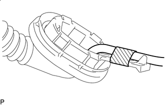
Tape Remove the tape to disconnect the antenna cord from the No. 2 wire harness protector.
-
Tape Remove the tape to disconnect the rubber protrusion of the grommet from the No. 2 wire harness protector.
-
-

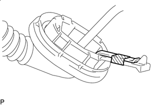
Remove in this Direction Separate the No. 1 wire harness protector from the grommet as shown in the illustration.
Tech Tips
Use the same procedure for the No. 2 wire harness protector.
-
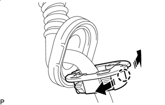
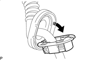
Remove in this Direction Disengage the claw as shown in the illustration and remove the No. 1 wire harness protector.
Tech Tips
Use the same procedure for the No. 2 wire harness protector.
-
-