STEERING WHEEL REMOVAL

CAUTION / NOTICE / HINT
The necessary procedures (adjustment, calibration, initialization, or registration) that must be performed after parts are removed, installed, or replaced during steering wheel assembly removal/installation are shown below.
| Replacement Part or Procedure | Necessary Procedures | Effects / Inoperative when not performed | Link |
|---|---|---|---|
| Disconnect cable from negative auxiliary battery terminal | Memorize steering angle neutral point | Lane departure alert system (w/ Steering Control) | |
| Intelligent clearance sonar system*1 | |||
| Simple intelligent parking assist system*1 | |||
| Pre-crash safety system | |||
| Adaptive high beam system | |||
| Parking assist monitor system | |||
| Initialize back door lock | Power door lock control system |
*1: When performing learning using the GTS.
Note
-
After the power switch is turned off, the radio and display receiver assembly records various types of memory and settings. As a result, after turning the power switch off, make sure to wait at least 90 seconds before disconnecting the cable from the negative (-) auxiliary battery terminal.
-
After the power switch is turned off, the navigation receiver assembly records various types of memory and settings. As a result, after turning the power switch off, make sure to wait at least 60 seconds before disconnecting the cable from the negative (-) auxiliary battery terminal.
-
When the cable has been disconnected and reconnected to the negative (-) auxiliary battery terminal, open and close the fuel lid before turning the power switch on (IG) (for w/ Canister Pump Module).
-
Do not replace the spiral cable with sensor sub-assembly with the auxiliary battery connected and the power switch on (IG).
-
Do not rotate the spiral cable with sensor sub-assembly without the steering wheel assembly installed with the auxiliary battery connected and the power switch on (IG).
-
Ensure that the steering wheel assembly is installed and aligned straight when inspecting the steering sensor.
PROCEDURE
-
ALIGN FRONT WHEELS FACING STRAIGHT AHEAD
-
REMOVE HORN BUTTON ASSEMBLY
-
REMOVE STEERING WHEEL ASSEMBLY
-
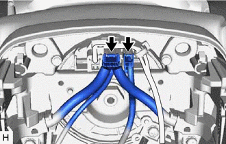
Disconnect 2 connectors from the spiral cable with sensor sub-assembly.
-
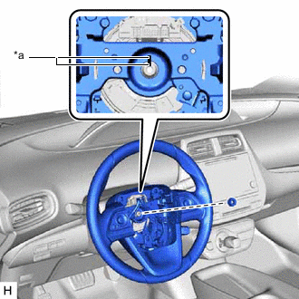
*a Matchmark Remove the steering wheel assembly set nut.
-
Put matchmarks on the steering wheel assembly and steering main shaft.
-
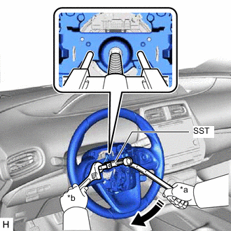
*a Turn *b Hold Using SST, remove the steering wheel assembly.
- SST
- 09950-50013 ( 09951-05010, 09952-05010, 09953-05020, 09954-05031 )
Note
Apply a small amount of grease to the threads and tip of SST (09953-05020) before use.
-
-
REMOVE CRUISE CONTROL MAIN SWITCH
-
REMOVE CRUISE CONTROL SWITCH WIRE
-
Remove the cruise control switch wire.
-
-
REMOVE STEERING PAD SWITCH ASSEMBLY
-
REMOVE STEERING WHEEL HEATER CONTROL ASSEMBLY (w/ Steering Heater)