POWER STEERING ECU(for LHD) REMOVAL
CAUTION / NOTICE / HINT
The necessary procedures (adjustment, calibration, initialization, or registration) that must be performed after parts are removed, installed, or replaced during power steering ECU assembly removal/installation are shown below.
| Replacement Part or Procedure | Necessary Procedures | Effects / Inoperative when not performed | Link |
|---|---|---|---|
| Disconnect cable from negative auxiliary battery terminal | Memorize steering angle neutral point | Lane departure alert system (w/ Steering Control) | |
| Intelligent clearance sonar system*1 | |||
| Simple intelligent parking assist system*1 | |||
| Pre-crash safety system | |||
| Adaptive high beam system | |||
| Parking assist monitor system | |||
| Initialize back door lock | Power door lock control system | ||
| Power steering ECU assembly |
|
|
*1: When performing learning using the GTS.
Note
-
After the power switch is turned off, the radio and display receiver assembly records various types of memory and settings. As a result, after turning the power switch off, make sure to wait at least 90 seconds before disconnecting the cable from the negative (-) auxiliary battery terminal.
-
After the power switch is turned off, the navigation receiver assembly records various types of memory and settings. As a result, after turning the power switch off, make sure to wait at least 60 seconds before disconnecting the cable from the negative (-) auxiliary battery terminal.
-
When the cable has been disconnected and reconnected to the negative (-) auxiliary battery terminal, open and close the fuel lid before turning the power switch on (IG) (for w/ Canister Pump Module).
-
Do not replace the spiral cable with sensor sub-assembly with the auxiliary battery connected and the power switch on (IG).
-
Do not rotate the spiral cable with sensor sub-assembly without the steering wheel assembly installed with the auxiliary battery connected and the power switch on (IG).
-
Ensure that the steering wheel assembly is installed and aligned straight when inspecting the steering sensor.
PROCEDURE
-
REMOVE STEERING COLUMN ASSEMBLY
-
REMOVE POWER STEERING ECU ASSEMBLY
Note
-
Do not drop the power steering ECU assembly, strike it with tools or subject it to impacts.
-
If the power steering ECU assembly is subjected to an impact, replace it with a new one.
-
Do not pull the wire harness of the electric power steering column sub-assembly.
-
Do not allow any moisture to come into contact with the power steering ECU assembly.
-
Do not loosen any bolts not mentioned in the procedure.
-
Do not allow any foreign matter to contaminate the power steering ECU assembly.
-
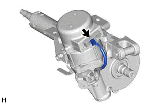
Disconnect the connector.
-
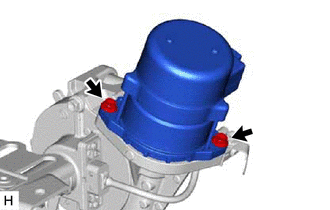
Remove the 2 bolts and power steering ECU assembly from the electric power steering column sub-assembly.
-
-
REMOVE ELECTRIC POWER STEERING MOTOR SHAFT DAMPER
-
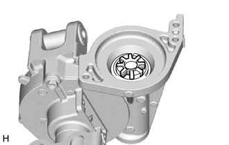
Remove the electric power steering motor shaft damper from the electric power steering column sub-assembly.
-