PARKING BRAKE CABLE(for Front Side) REMOVAL
CAUTION / NOTICE / HINT
The necessary procedures (adjustment, calibration, initialization, or registration) that must be performed after parts are removed and installed, or replaced during No. 1 parking brake cable assembly removal/installation are shown below.
| Replaced Part or Performed Procedure | Necessary Procedure | Effect/Inoperative Function when Necessary Procedure not Performed | Link |
|---|---|---|---|
| Auxiliary battery terminal is disconnected/reconnected | Memorize steering angle neutral point | Lane departure alert system (w/ Steering control) | |
| Intelligent clearance sonar system*1 | |||
| Simple intelligent parking assist system*1 | |||
| Pre-crash safety system | |||
| Adaptive high beam system | |||
| Parking assist monitor system | |||
| Initialize back door lock | Power door lock control system | ||
| Replacement of brake pedal stroke sensor assembly |
|
|
for Initialization: for Calibration: |
*1: When performing learning using the GTS.
Note
While the auxiliary battery is connected, even if the power switch is off, the brake control system activates when the brake pedal is depressed or any door courtesy switch turns on. Therefore, when servicing the brake system components, do not operate the brake pedal or open/close the doors while the auxiliary battery is connected.
PROCEDURE
-
PRECAUTION
Note
After turning the power switch off, waiting time may be required before disconnecting the cable from the negative (-) auxiliary battery terminal. Therefore, make sure to read the disconnecting the cable from the negative (-) auxiliary battery terminal notices before proceeding with work.
-
REMOVE PARKING BRAKE PEDAL ASSEMBLY (for LHD)
-
REMOVE PARKING BRAKE PEDAL ASSEMBLY (for RHD)
-
REMOVE FRONT CONSOLE BOX MOUNTING BRACKET
-
Disengage the 2 clamps.
-
Remove the 2 bolts and front console box mounting bracket.
-
-
REMOVE SOLAR BATTERY (w/ Solar Charging System)
-
REMOVE NO. 1 SOLAR BATTERY MOUNT BRACKET (w/ Solar Charging System)
-
Disengage the 2 clamps.
-
Turn back the front floor carpet assembly.
-
Remove the 4 bolts and No. 1 solar battery mount bracket.
-
-
REMOVE INVERTER BATTERY (w/ Canister Pump Module)
-
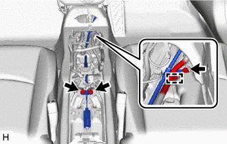
SEPARATE NO. 1 PARKING BRAKE CABLE ASSEMBLY
-
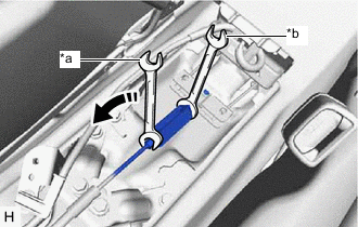
*a Turn *b Hold Separate the No. 1 parking brake cable assembly from the No. 1 parking brake pull rod sub-assembly as shown in the illustration.
-
-
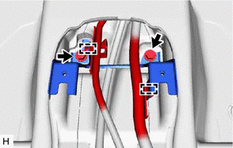
REMOVE NO. 1 PARKING BRAKE CABLE ASSEMBLY (for LHD)
-
Disengage the 2 clamps.
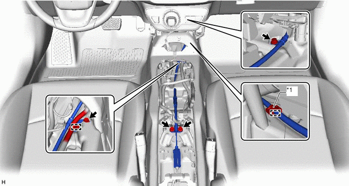
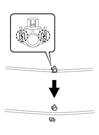
*1 Front Parking Brake Cable Clamp - - Tech Tips
The front parking brake cable clamp cannot be reused once removed. Make sure to remove it from the No. 1 parking brake cable clamp assembly.
-
Remove the 4 bolts and No. 1 parking brake cable assembly.
-
-
REMOVE FRONT PARKING BRAKE CABLE CLAMP (for LHD)
-
for One-piece type front parking brake cable clamp:
-
Using pliers or equivalent, disconnect the front parking brake cable clamp and remove it from the No. 1 parking brake cable assembly.
-
-
for Separate type front parking brake cable clamp:
-
Disengage the 2 claws to remove the front parking brake cable clamp from the No. 1 parking brake cable assembly.
-
-
-
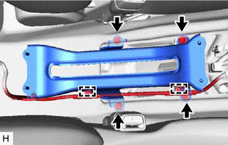
REMOVE NO. 1 PARKING BRAKE CABLE ASSEMBLY (for RHD)
-
Disengage the clamp.
-
Remove the 3 bolts and No. 1 parking brake cable assembly.
-