PARKING BRAKE PEDAL(for LHD) REMOVAL
CAUTION / NOTICE / HINT
The necessary procedures (adjustment, calibration, initialization, or registration) that must be performed after parts are removed and installed, or replaced during parking brake pedal assembly removal/installation are shown below.
| Replaced Part or Performed Procedure | Necessary Procedure | Effect/Inoperative Function when Necessary Procedure not Performed | Link |
|---|---|---|---|
| Auxiliary battery terminal is disconnected/reconnected | Memorize steering angle neutral point | Lane departure alert system (w/ Steering control) | |
| Intelligent clearance sonar system*1 | |||
| Simple intelligent parking assist system*1 | |||
| Pre-crash safety system | |||
| Adaptive high beam system | |||
| Parking assist monitor system | |||
| Initialize back door lock | Power door lock control system | ||
| Replacement of brake pedal stroke sensor assembly |
|
|
for Initialization: for Calibration: |
*1: When performing learning using the GTS.
Note
While the auxiliary battery is connected, even if the power switch is off, the brake control system activates when the brake pedal is depressed or any door courtesy switch turns on. Therefore, when servicing the brake system components, do not operate the brake pedal or open/close the doors while the auxiliary battery is connected.
PROCEDURE
-
PRECAUTION
Note
After turning the power switch off, waiting time may be required before disconnecting the cable from the negative (-) auxiliary battery terminal. Therefore, make sure to read the disconnecting the cable from the negative (-) auxiliary battery terminal notices before proceeding with work.
-
DISCONNECT CABLE FROM NEGATIVE AUXILIARY BATTERY TERMINAL
-
LOOSEN NO. 1 WIRE ADJUSTING NUT
-
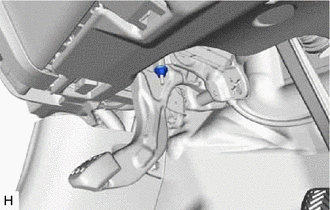
Loosen the No. 1 wire adjusting nut.
Note
If the No. 1 wire adjusting nut has been removed from the No. 1 parking brake cable assembly, replace the No. 1 wire adjusting nut with a new one.
-
-
REMOVE NO. 1 INSTRUMENT PANEL UNDER COVER SUB-ASSEMBLY
-
REMOVE REAR CONSOLE BOX ASSEMBLY (w/o Solar Charging System)
-
REMOVE REAR CONSOLE BOX ASSEMBLY (w/ Solar Charging System)
-
REMOVE LOWER CENTER INSTRUMENT CLUSTER FINISH PANEL SUB-ASSEMBLY
-
REMOVE FRONT NO. 1 CONSOLE BOX INSERT
-
REMOVE FRONT NO. 2 CONSOLE BOX INSERT
-
REMOVE NO. 1 AIR DUCT
-
REMOVE FRONT DOOR SCUFF PLATE LH
-
REMOVE COWL SIDE TRIM BOARD LH
-
REMOVE INSTRUMENT PANEL FINISH PANEL END LH
-
REMOVE INSTRUMENT CLUSTER FINISH PANEL GARNISH ASSEMBLY
-
DISCONNECT HOOD LOCK CONTROL LEVER SUB-ASSEMBLY
-
REMOVE LOWER INSTRUMENT PANEL FINISH PANEL ASSEMBLY
-
REMOVE BRAKE PEDAL STROKE SENSOR ASSEMBLY
-
SEPARATE NO. 1 PARKING BRAKE CABLE ASSEMBLY
-
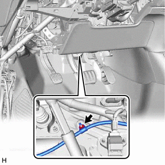
Remove the nut and separate the No. 1 parking brake cable assembly.
-
-
SEPARATE PARKING BRAKE PEDAL ASSEMBLY
-
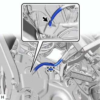
Disengage the clamp.
-
Disconnect the parking brake switch connector.
-
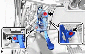
Remove the bolt and 2 nuts, and separate the parking brake pedal assembly from the vehicle body.
-
-
REMOVE PARKING BRAKE PEDAL ASSEMBLY
-
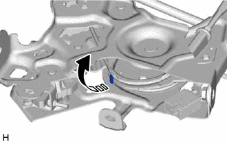
Pull up the parking brake pedal assembly claw.
Note
Do not damage the No. 1 parking brake cable assembly.
-
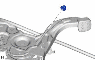
Remove the No. 1 wire adjusting nut from the No. 1 parking brake cable assembly.
Note
If the No. 1 wire adjusting nut has been removed from the No. 1 parking brake cable assembly, replace the No. 1 wire adjusting nut with a new one.
-
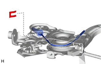
Remove the clip from the No. 1 parking brake cable assembly.
-
Remove the parking brake pedal assembly from the No. 1 parking brake cable assembly.
-